Worklog Xii-Boy Ultra V3 - JechtZ Build Adventure

JechtZ

.
Joined
Mar 9, 2026
Messages
16
Likes
31
Hello all!

I've been a bit active on the discord lately but havnt posted much on here on forums yet.

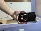
I'm take a stab at building the Xii-Boy Ultra (BETA V3). Looking at all the other builds - the mess of wires was beyond intimidating. After reading this project was mainly ribbon cables and soldering smd to boards, I realized I can tackle this. I've done enough modding and repair work to do that much.

Dealing with Gerber's files and orders pcbs was beyond daunting but Xenii hasn't appeared to get annoyed with my constant need for validation in his DMs.

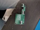
Today, after a flurry of complaining emails with JLCPCB, my production has started on two shells and 5 sets of PCBs (minimum I guess).

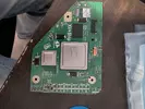
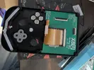
I've also ordered a pair of wii's with disk drive issues on eBay/Mercari. I put in my 4LT order, AliExpress, digikey and also going to try to utilize mxHound chip relocation cause Animal Crossing is an absolute must for me. Will need to figure out how that fits in.

I also snagged a hotplate from AliExpress that Xenii appeared to be using. Seems useful for getting ribbon latches attached.

It's going to be an adventure. Hope you'll enjoy with me.
 
I got my 4 layer board in the mail today. I went through the Homebrew process but I wasn't quite sure what applications to install as Rvloader fails to mention what step to stop at beyond saying you need homebrew.

I wanted to backup my nand so I installed bootmii and priiloader but later found out priiloader appears to be part of RVLoader?

I've taken apart wii's for repairs in past so this isn't new to me but I've followed the motherboard replacement guide on iFixit for those that are unfamiliar with the process.
 
  • Like
Reactions: cy
I got my 4 layer board in the mail today. I went through the Homebrew process but I wasn't quite sure what applications to install as Rvloader fails to mention what step to stop at beyond saying you need homebrew.

I wanted to backup my nand so I installed bootmii and priiloader but later found out priiloader appears to be part of RVLoader?

I've taken apart wii's for repairs in past so this isn't new to me but I've followed the motherboard replacement guide on iFixit for those that are unfamiliar with the process.
All you need to install up to is the Homebrew channel, then you can install RVLoader. Unless you want to create a NAND backup though. In that case, you can create the backup with Bootmii, but I don't believe you're supposed to install Priiloader. It's probably going to be fine, but just in case you could always load the NAND backup that you just created.
 
  • Like
Reactions: cy
Confirmed Priiloader is part of RVLoader so not too concerned and its installed as part of it.

I loaded up all my games to the USB drive and had a number of issues.

In testing pre-trim cuts I missed completely that B is 1 on the wii mote which is a bit confusing for trying to setup per-game settings but lesson learned.

Couldn't figure out why Wii games wouldn't work what so ever when in them. Bluetooth is turned off by default! I feel like that's a major setting to have in per settings instead of per-game but alas I'm late to the party.

I need to go get a diamond wheel from the store tomorrow and take apart the console to get the board out. Already got the sandpaper from a previous trip.

Tired and off to bed.
 
Bluetooth is off by default due to the patch that lets Gamecube controller inputs be translated into (most) Wiimote inputs. The default config assumes you're using emulated inputs instead a physical Wiimote, so yeah you will have to enable bluetooth for each Wii game that you want to use a Wiimote for.

Would be nice if there was a setting to change that default.
 
Update time.

I got my cpu-40 wii taken apart.

I went and bought a diamond wheel for my dremel I've never used and starting cutting.

I ended up cutting inside the outline in some parts and nearly destroyed the cap by the NAND.

I removed the cap while sanding and restarted it afterwards. I sanded from 120 to 320 to 600 to 800.

I checked all my resistances per the guide and they all more or less matched up. Not the straightest cuts.

Some things missing from the Definitive guide is removable components and a picture of what the end state looks like back and forth. Found that frustrating. Bryce gave me a guide for the Xii-Boy Ultra to help beta test which has some of this information. I removed most of the audio components, LDO, the electrolytic caps and various others.

Not sure exactly how U5 to U10 relocation works with the Xii-Boy Ultra and the PMS2. I need to do further research of Xenii's and Bryce's previous worklogs.

My order from digikey has arrived with part of pcm bom but I'm still waiting for the other supplies so I cannot proceed further.

Let me know what you think.
 

Attachments

  • PXL_20260322_142629756.webp
    PXL_20260322_142629756.webp
    1.9 MB · Views: 8
  • PXL_20260322_142651591.webp
    PXL_20260322_142651591.webp
    2.1 MB · Views: 11
  • PXL_20260322_143622902.webp
    PXL_20260322_143622902.webp
    691.5 KB · Views: 18
Just wanted to quickly note that the Xii-Boy Ultra uses the PMS's U10 emulation rather than relocation. Sorry that the Xii-Flex section isn't completed yet, I plan on finishing that sometime this week and uploading it to the guide.

Really excited to see how of this build. Glad you were able to trim it successfully, hopefully the trim turns on!
 
Yeah Bryce just told me in DM this morning.

I also ordered mxHound relocation flexes as playing Animal Crossing is sort of a must. So I'll have to figure out out how to integrate that.
 
Losing the second NAND cap isn't ideal and can cause boot/loading faults, but it is relatively simple to resolve if it becomes a problem
 
I didn't lose it luckily. Removed it while I sanded but it's at edge of a Cliff after I repopulated.

My 4 layer tech order came today. My jlcpcb order should be here Tuesday. Already got my digikey order and just waiting on my AliExpress order.

Should at least start populating the boards next week!
 

Attachments

  • 17745666737987083941481630255996.webp
    17745666737987083941481630255996.webp
    146.3 KB · Views: 11
Looks like you've sanded partway through the 3.3v and GND supply vias there. If you have boot troubles, you can run a 3.3v and a GND wire to the cap directly to restore function to that side of the chip
 
Been a bit and been working on this last few days.

Xii Strip was more difficult than I imagined. I couldn't get enough solder to connect between pad and the voltage thingies. Ended up removing it and building up the solder and then moving it over and then I used my chisel tip I never use and suddenly things were working good. No shorts.

Then I got the DD board soldered together and tested for shorts. I bridged the hell out of everything to start and had to remove everything, carefully wick the connectors. I placed on board, hot aired the connectors from bottom and then checked pin by pin to ensure they were soldered solidly.

The rvl-dd seemed to be easy but shorted ground and 54 somehow and had to wick and hot air to remove. Noticing others they appeared to solder the top and allow it flow down the hole instead of on side like I did. Maybe I'm wrong but no shorts on here finally.

I put the screen(they were out of black outlines) in the front shell, wire mesh, speakers and buttons all in place.

I need to wire up the rumble motor with the appropriate connector and then I can strap down those bottom items.

I soldered up the trigger board super quick. No issues there.

But I somehow missed ordering a bunch of items including on main board and the controller board so had to put in another order or two. Which is fine because I want to build at least two of these.

Progressing!
 

Attachments

  • 17754426099794580525126283563021.webp
    17754426099794580525126283563021.webp
    136.2 KB · Views: 10
  • 17754426014869051603624021197638.webp
    17754426014869051603624021197638.webp
    201.7 KB · Views: 11
  • 17754425264345204004715675660751.webp
    17754425264345204004715675660751.webp
    302.4 KB · Views: 7
  • 1775442493931870098811209885383.webp
    1775442493931870098811209885383.webp
    260 KB · Views: 6
I got my digikey order in with the parts I missed and I finished soldering up the controller PCB.

I thought I had some shorts but didn't verify via the PCB design but wasted several hours on expected behavior connectivity. Lesson learned.

I scrapped the board and will have to order some solder mask to fix it but other than that, another one done.

7696.webp
7695.webp
 
I got the front half done, though it came with some frustration. The 4mm screws on the first shell stripped out because I was inserting them too fast. Most of them didn’t bite properly, and I kept turning, which didn’t help.

I spoke with Xenni, and he’s going to start recommending 1.2mm board size instead of 1.6mm for the controller board going forward.

I'm dreaming of threaded inserts, but overall the second backup shell I ordered worked much better as I carefully screwed in. Everything seated fine except for one of the joystick holes, which did strip. I’m hoping there’s enough support behind it to keep it from pushing through.

The good news is that everything transfers over to a new shell pretty easily, so reworking things isn’t too painful down the road. I may try a different material next time—this one is Imagine Black. Red Herring on Discord also suggested using a bit of grease on the screws, which supposedly helps a lot, so I’ve ordered some to try.

I also ordered a full-size hot plate since the mini one I got from AliExpress hasn’t been great. I really wasn’t looking forward to doing the 40- and 50-pin connectors by hand like I did with the rest of the board.

On top of that, the flux I’ve been using (also from AliExpress) is pretty rough—super messy and hard to clean—so I picked up some higher-quality flux based on Y2K’s recommendation.

One last thing: the speaker wires are pretty short, so I may need to extend one of them.

Waiting on some parts for the main PCB.

Appreciate all the support from everyone so far.


7702.webp


7701.webp
 
Been active on discord but not on here.

I got the main board put together but I was having issues with powering on. It would drop to 1.2v on B+ and B- on the BMS. I tried replacing U4 and U5 but no change. It would power on with USB-C and get fan spin but not with batteries and it would charge extremely slow.

PXL_20260424_142829956.webp
PXL_20260423_223319769.webp


After showing some pictures - we identified inefficient solder on U4, U5, the resistors around it also seemed sparse so I got them filled out considerably. I think R6 was the primary cause of this. So I put everything together and got strange screen but it was progress.

rn_image_picker_lib_temp_7836382a-bbb0-4429-8313-28ce3bc32ac0.webp

I assumed right away I likely have some connections on the Xii Ultra Flex that aren't making it but I couldn't find any resources for the Xii Ultra pin out to where it went on the AVE. So I edited the PCB files and referred to a pin out that Yveltal had linked with their AVE Flex.

screenimage.webp
AVE pin out.webp

AVE pin out 2.webp

I built my own table to reference based on the above images to then go pin by pin to check for continuity. Wifi and GPI01 were clear enough I didn't really have get super detailed on them as they more or less went sequentially but maybe somebody else can provide more details for me to edit the table.

Ultra Flex 1.webp
ultra flex 2.webp


With these I was able to easily test from the AVE to the end of the flex which connections weren't working and it turned out to be 3 of them.

Once it was all soldered up and verified with continuity. We are up and running minus waiting on LEDs and thermistor. The buttons for some reason weren't working either so I just added additional solder to the GC 2.0 as it wasn't as thick as I'd like.

rn_image_picker_lib_temp_cc426418-be25-4e25-b985-a642db8a0067.webp


Now everything appears to work other then my left stick where the screw holes are stripped out and that stick is inverted. I need to epoxy the shell to be able to hopefully have enough material to screw into and then run the calibration but we're almost there!
 

Attachments

  • AVE pin out 2.webp
    AVE pin out 2.webp
    80.1 KB · Views: 6
Back
Top