

Vectronix - A Custom Vector CRT Game System
Introduction:
Around December of 2025 and January of 2026, I fiddled with the idea of creating a Vector CRT similar to the Vectrex. I had a good starting point with custom amplifiers that I made, but they didn't really go anywhere—so I'm starting again here hopefully to finish it! This project was intended to be my submission for the 2026 BitBuilt Summer Competition, but I got stuck with some issues that I thought I should wait on. I've since then added a bunch of progress images from January of 2026, and I plan to continue updates. I'm making lots of progress, so if you're interested, please Like this post!
I really appreciate that I won 3rd place in the 2025 Summer Competition, that seriously means the world! Thanks so much everyone for your support on my previous projects.
1/8/2026:
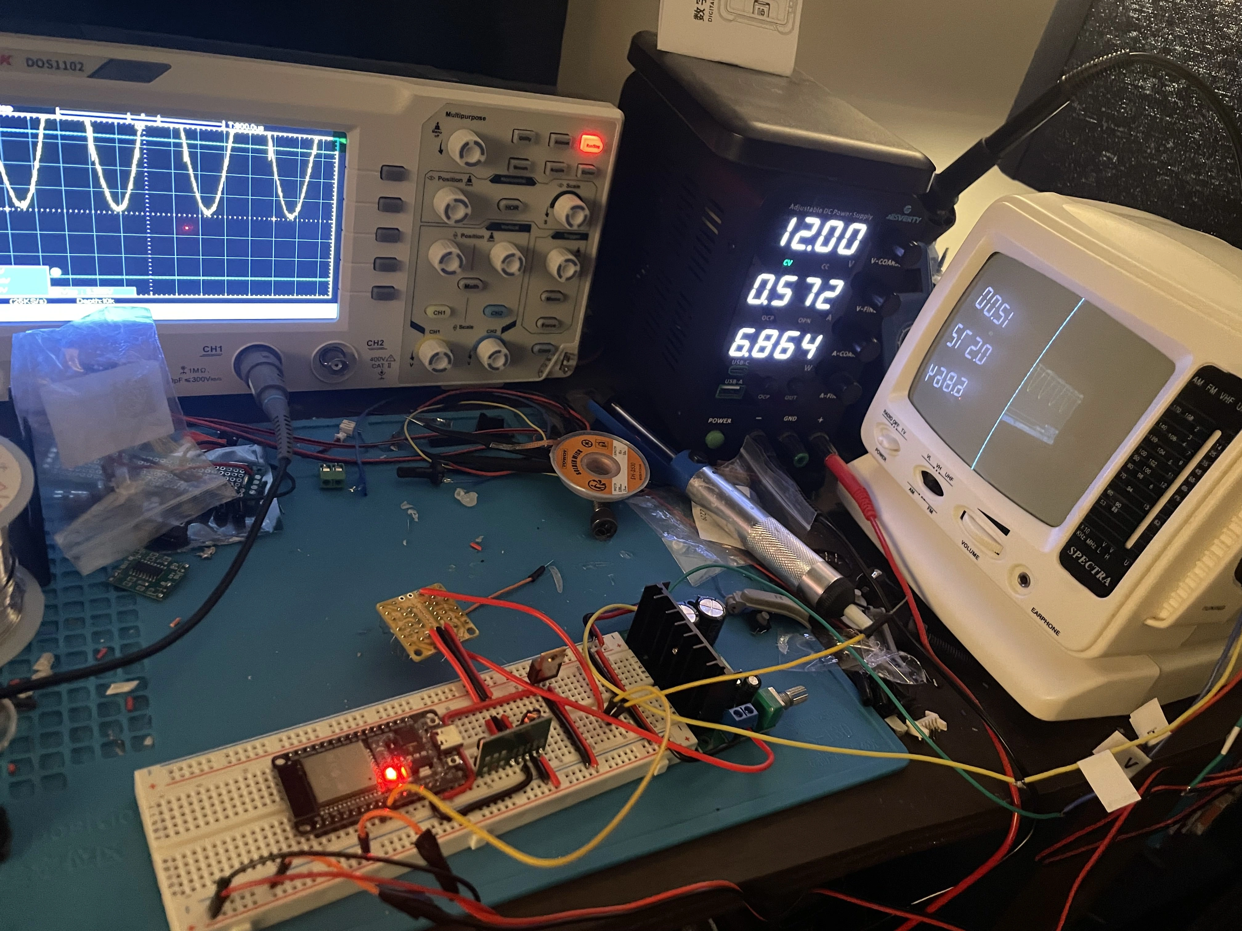
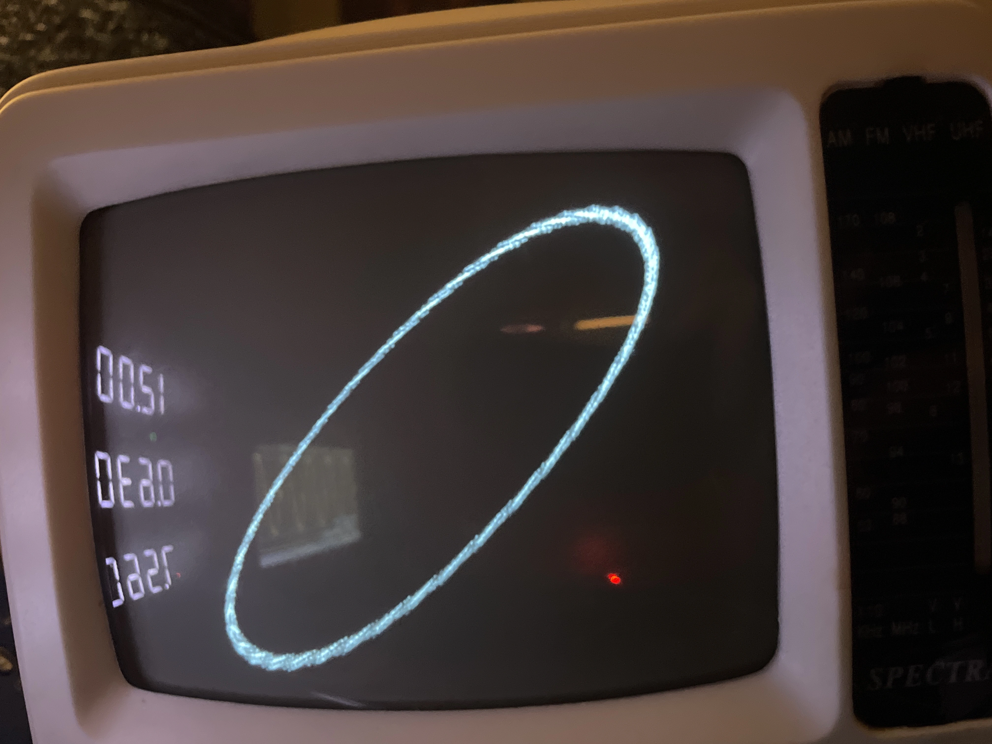
A CRT TV draws images in a line-by-line format sort of like a printer. That format of drawing images is called a raster image. Old Atari Games and the Vectrex use a vector CRT that only draws images from point to point. This removes the ability of drawing standard video, but allows for really neat glowing lines and bullets in games that can't be found or replicated any other way. A vector monitor works similar to how a Tube oscilloscope works in XY mode. I hijacked the inputs off of the raster yoke (the magnetic pair of inductors that steer the beam in the X and Y direction, one coil for each axis). I bought an audio amplifier pair using the TDA2050 (similar to the amplifiers out of a laser galvanometer).
1/11/2026:
The issue with the current amplifiers are that they are AC-coupled, which doesn't work for drawing vector graphics since sharp corners can get smoothed out from capacitors in the circuit, so I modded the amps for each axis. I also bought a cheap DC-in switching power supply, since the axes work like a 2D coordinate grid, to move the beam negative, the beam needs to be driven with a negative voltage.
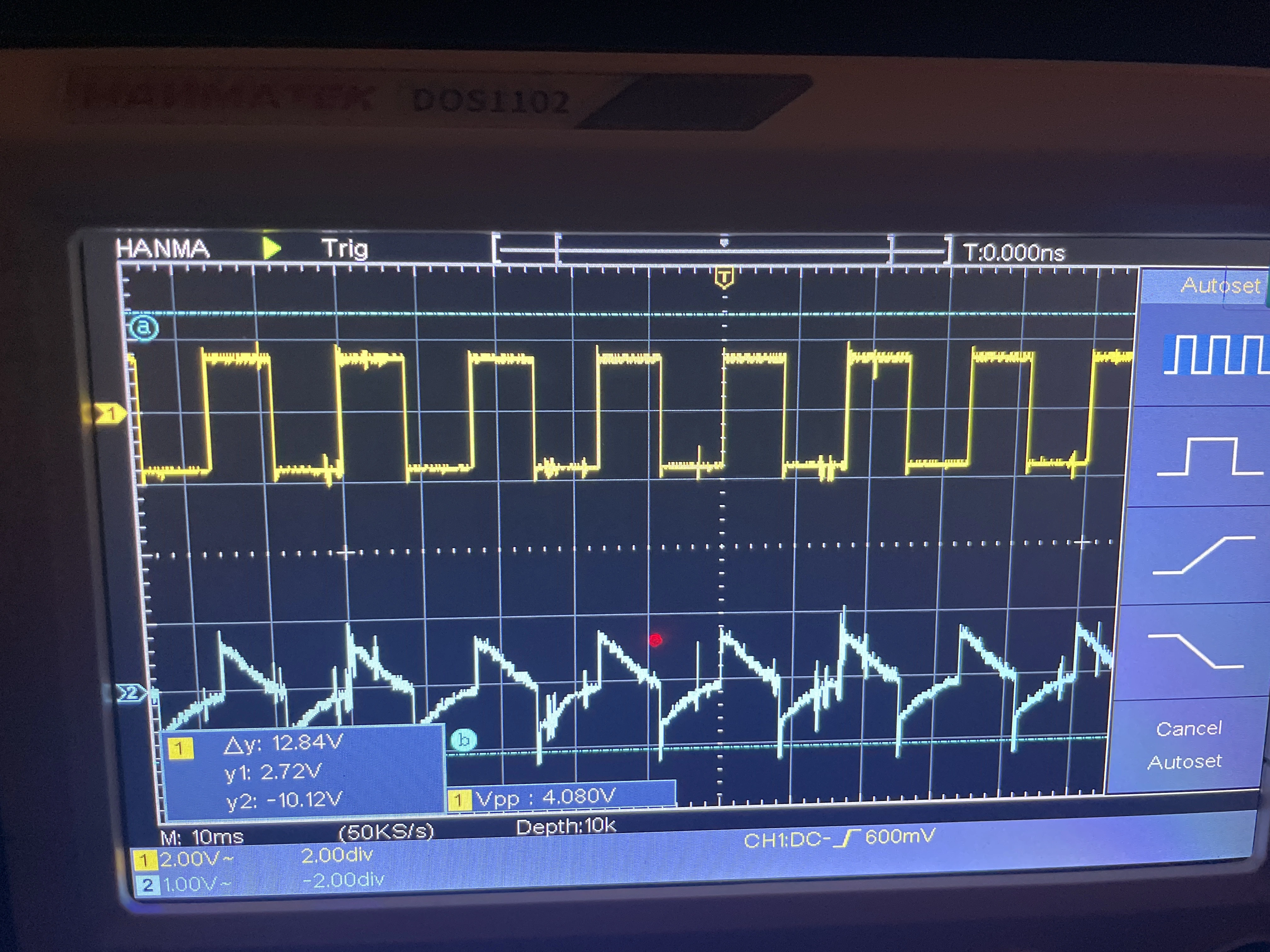
You can see the issue with the AC coupling vs. the DC coupling. The yellow channel is the signal out of the ESP32, and the blue signal is out of the amplifier. See the signal corners getting rounded off?
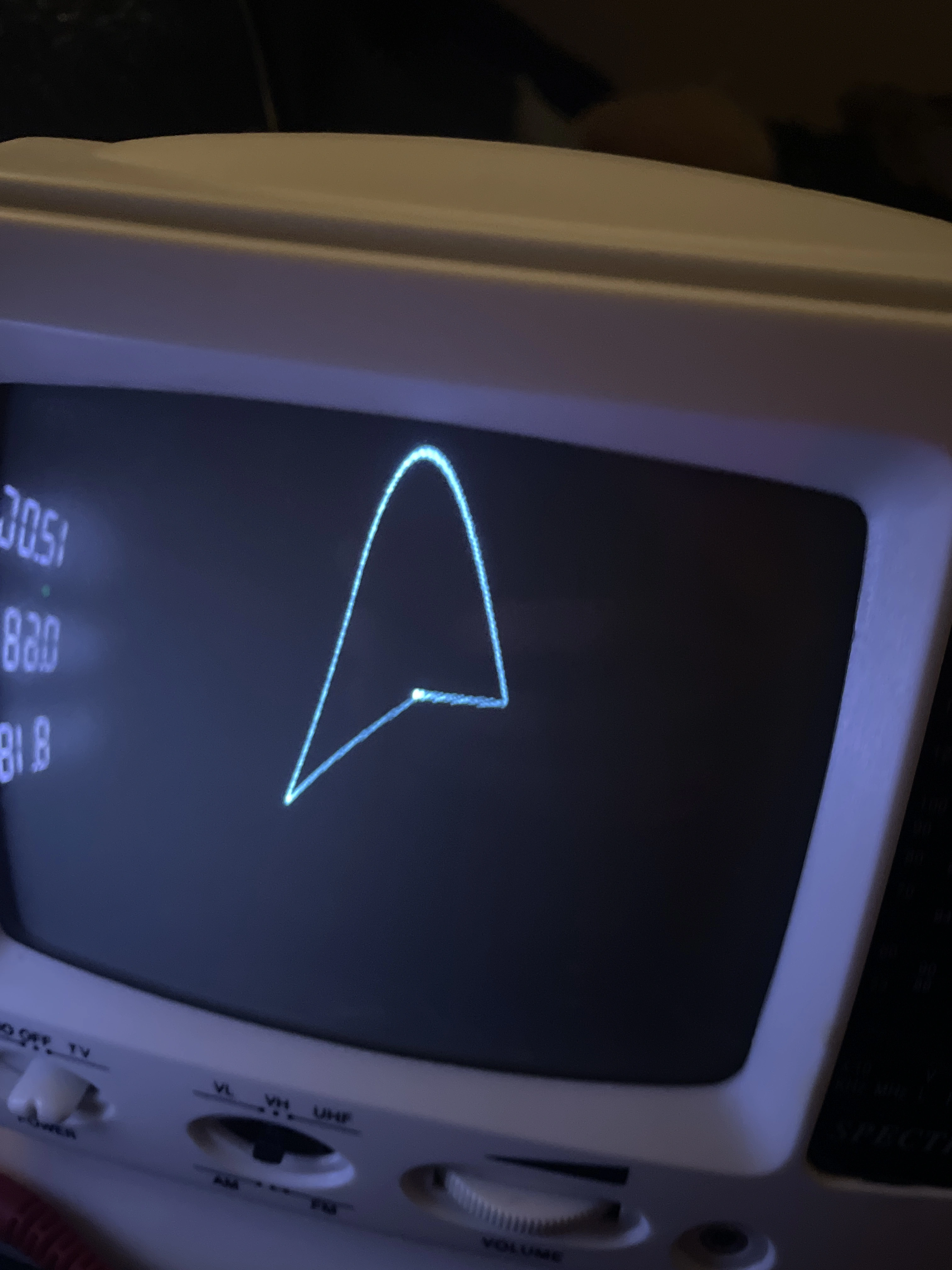
The circuit trying to draw the letter "A".
1/13/2026:
I thought that some of the distortion could be because the yoke was a raster yoke. Basically, a vector yoke has the same inductance and resistance values across both axes, the yoke in a raster CRT usually can't make those quick jumps since the only thing that has to move super fast is the horizontal coil compared to the small movement that the vertical coil makes.
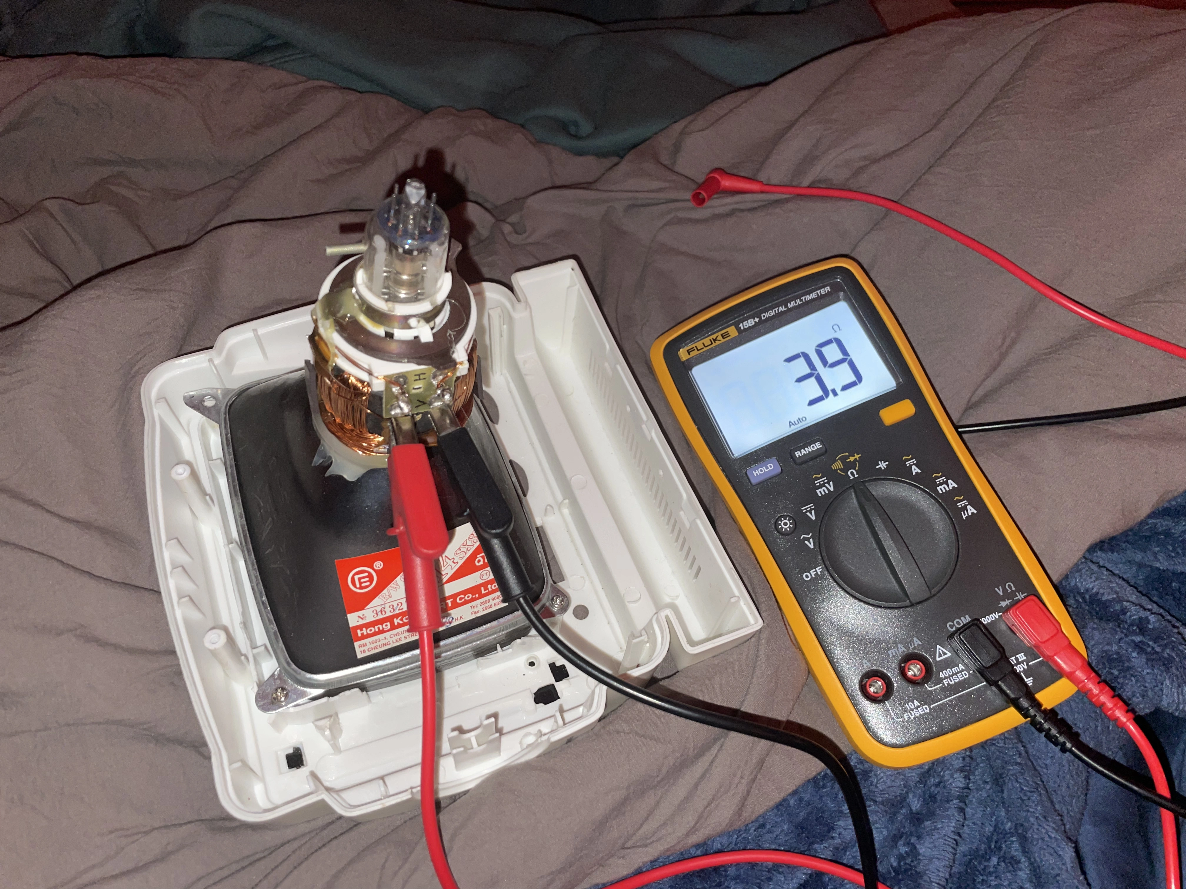
The resistance of the Vertical Coil in ohms.
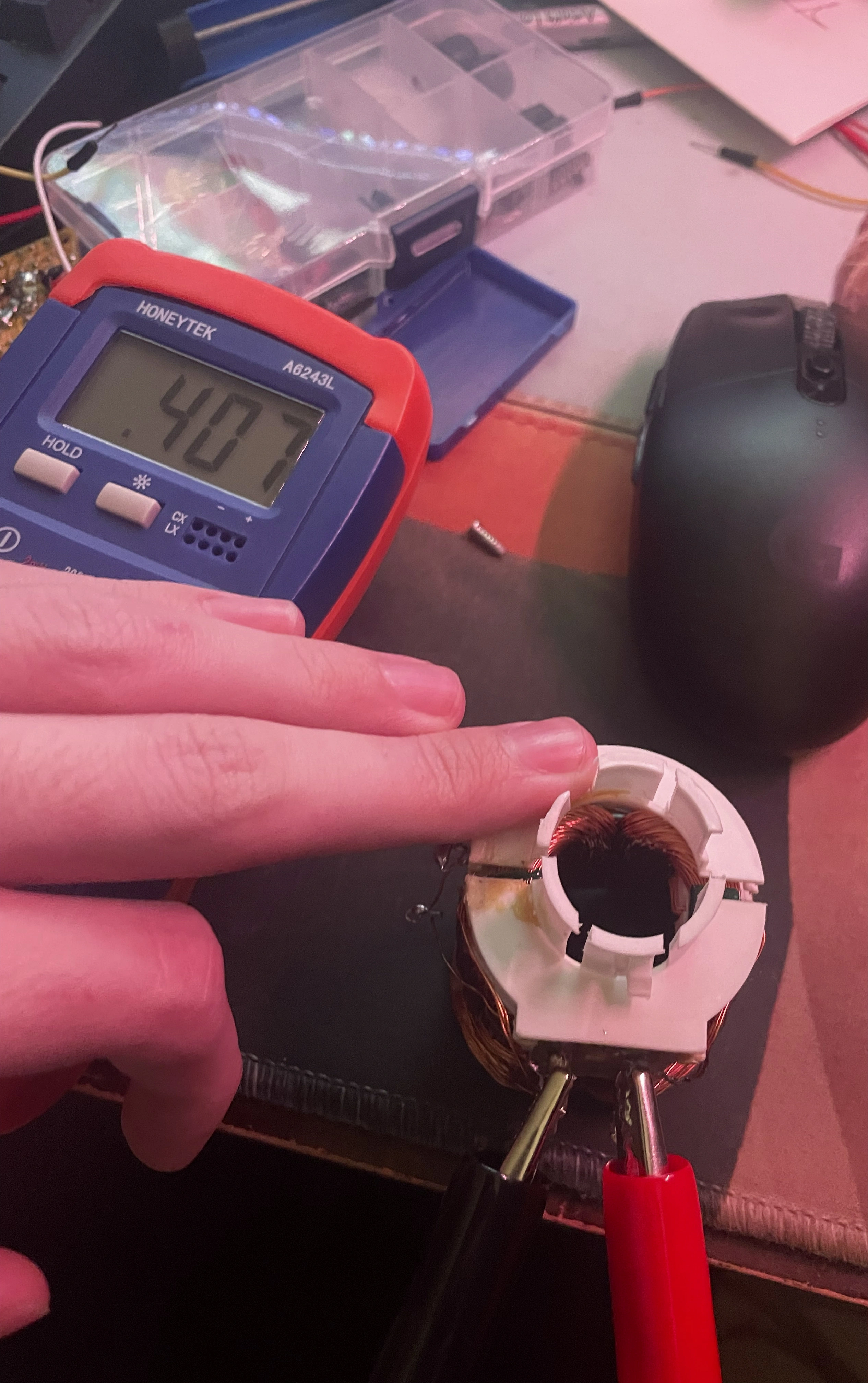
The inductance of the Horizontal Coil in mH.
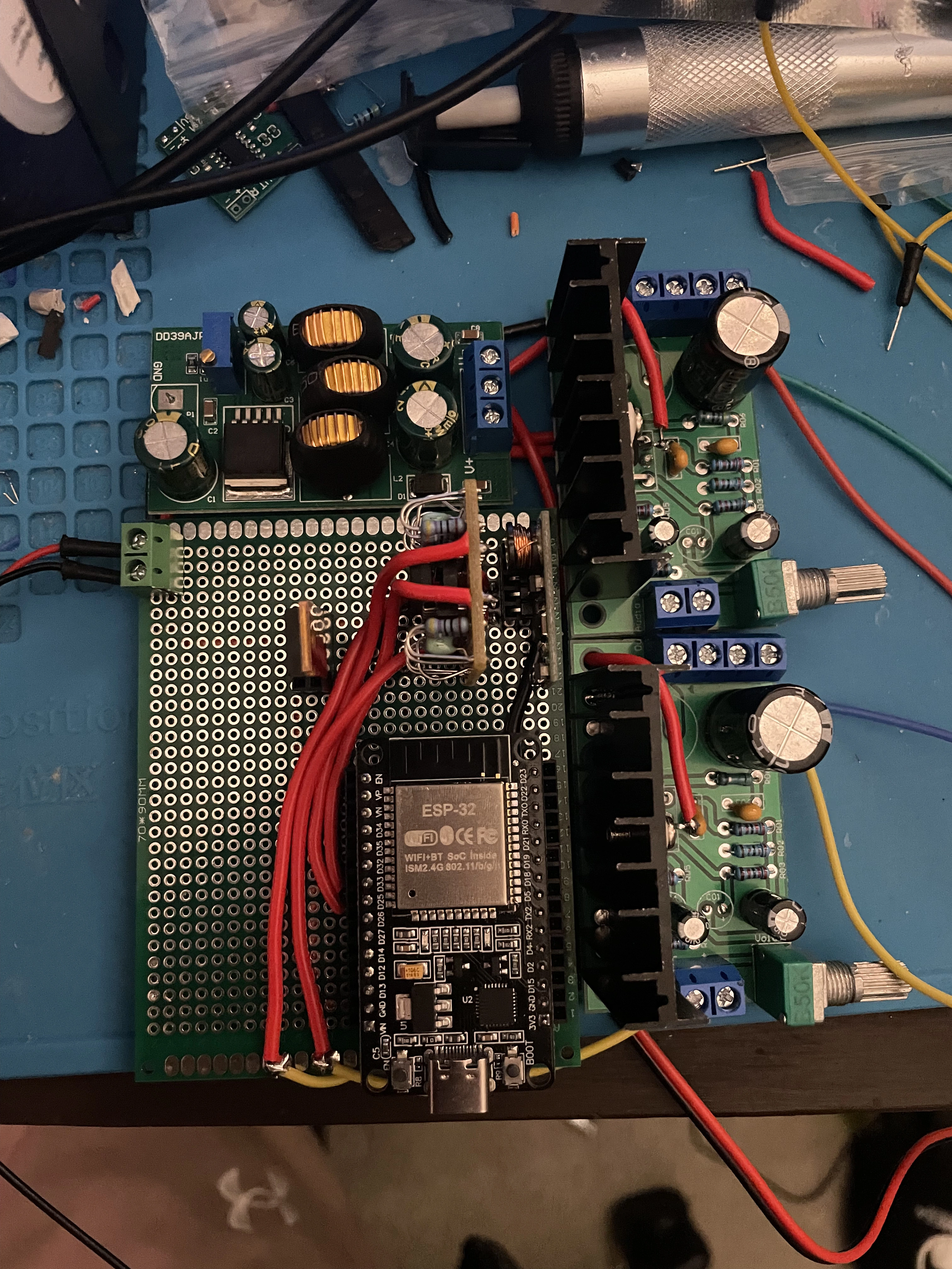
I also wired the circuit on prototyping board, which was way better than working with breadboards. Also, breadboards can have stray capacitance, which is not good for vector signal integrity.
1/26/2026:
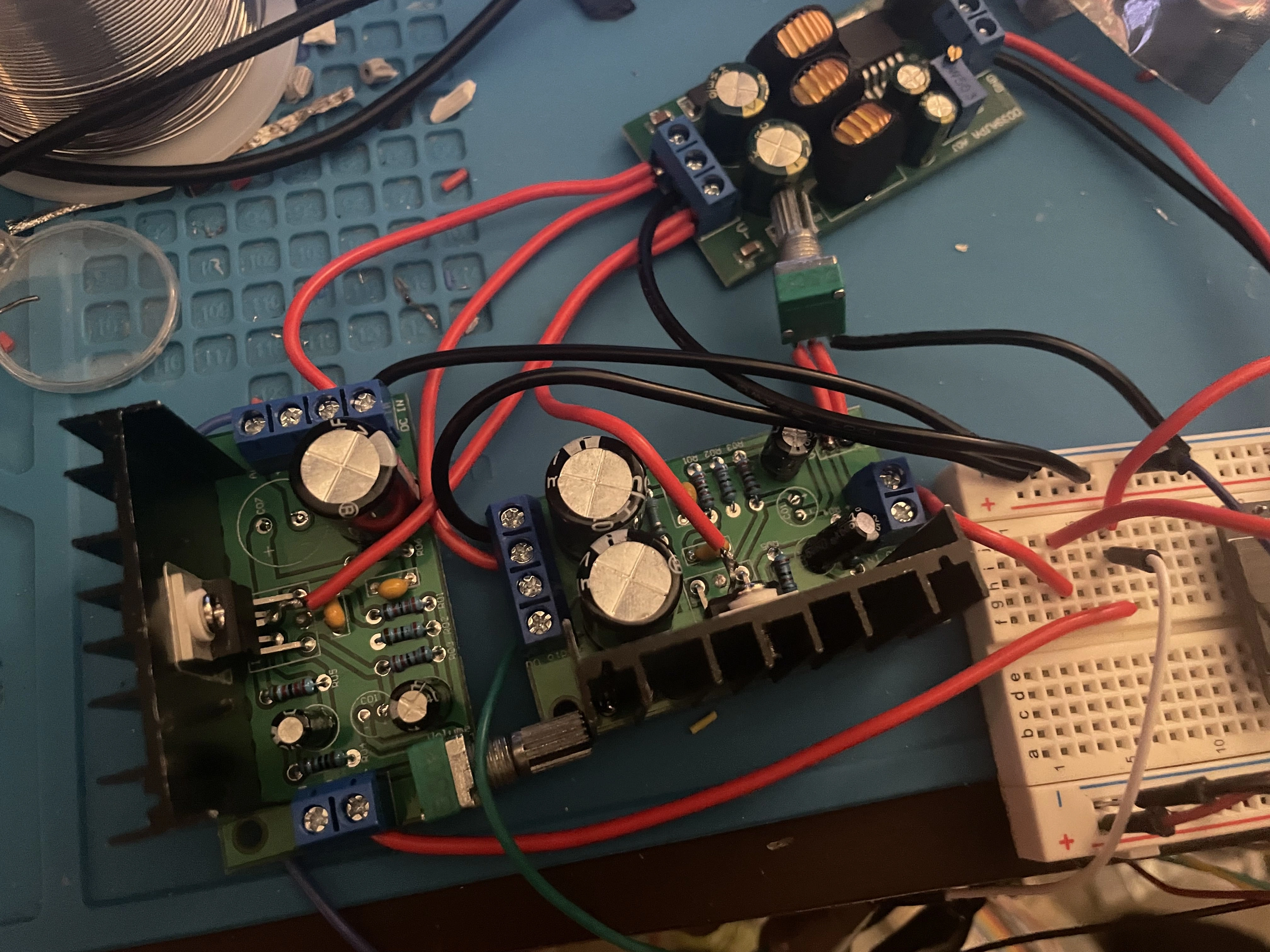
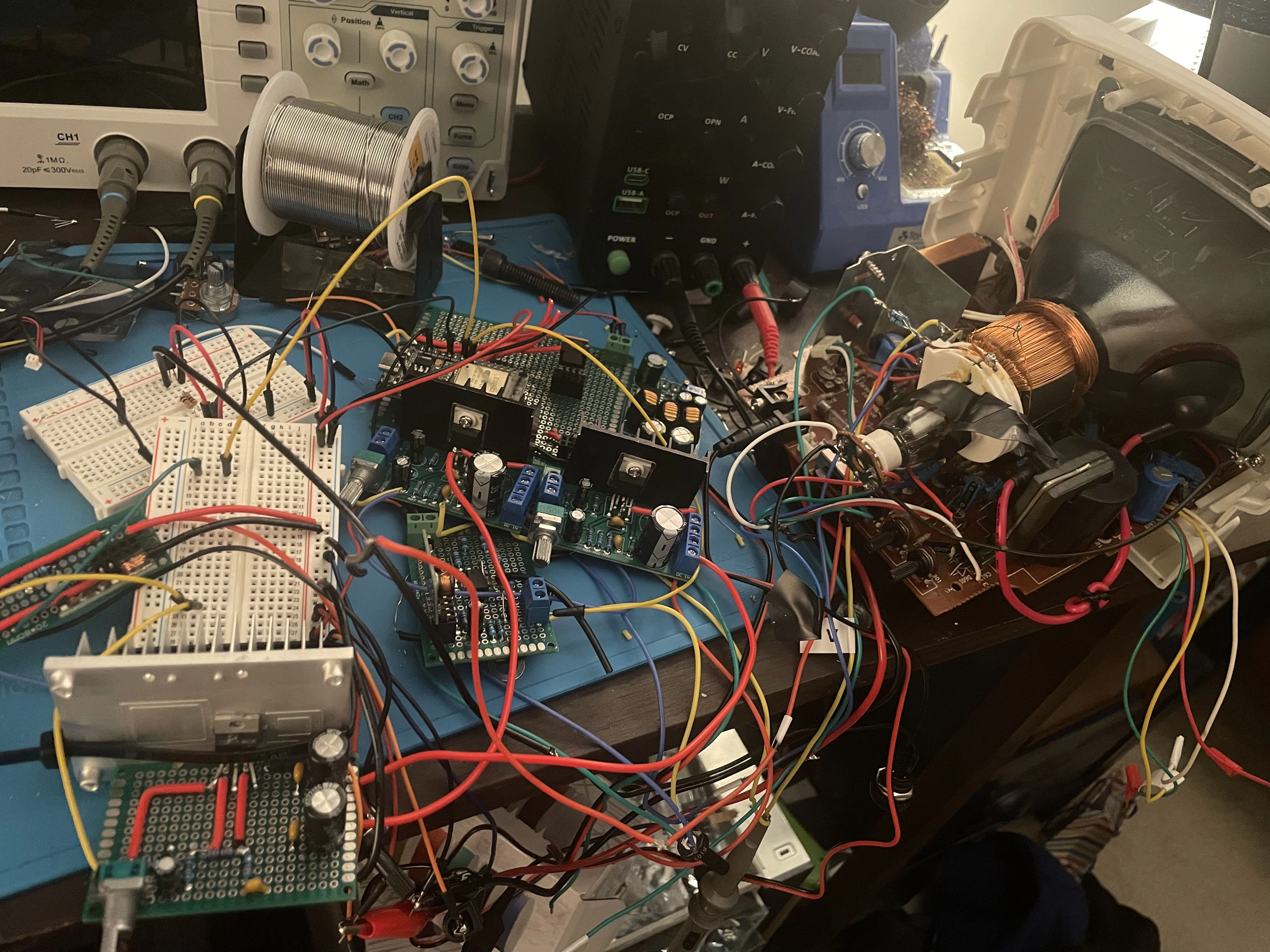
I redesigned the amplifier boards with the DC-coupling parts with some help from @cheese. Here is the spaghetti-mess of wires that is testing this project.
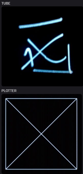
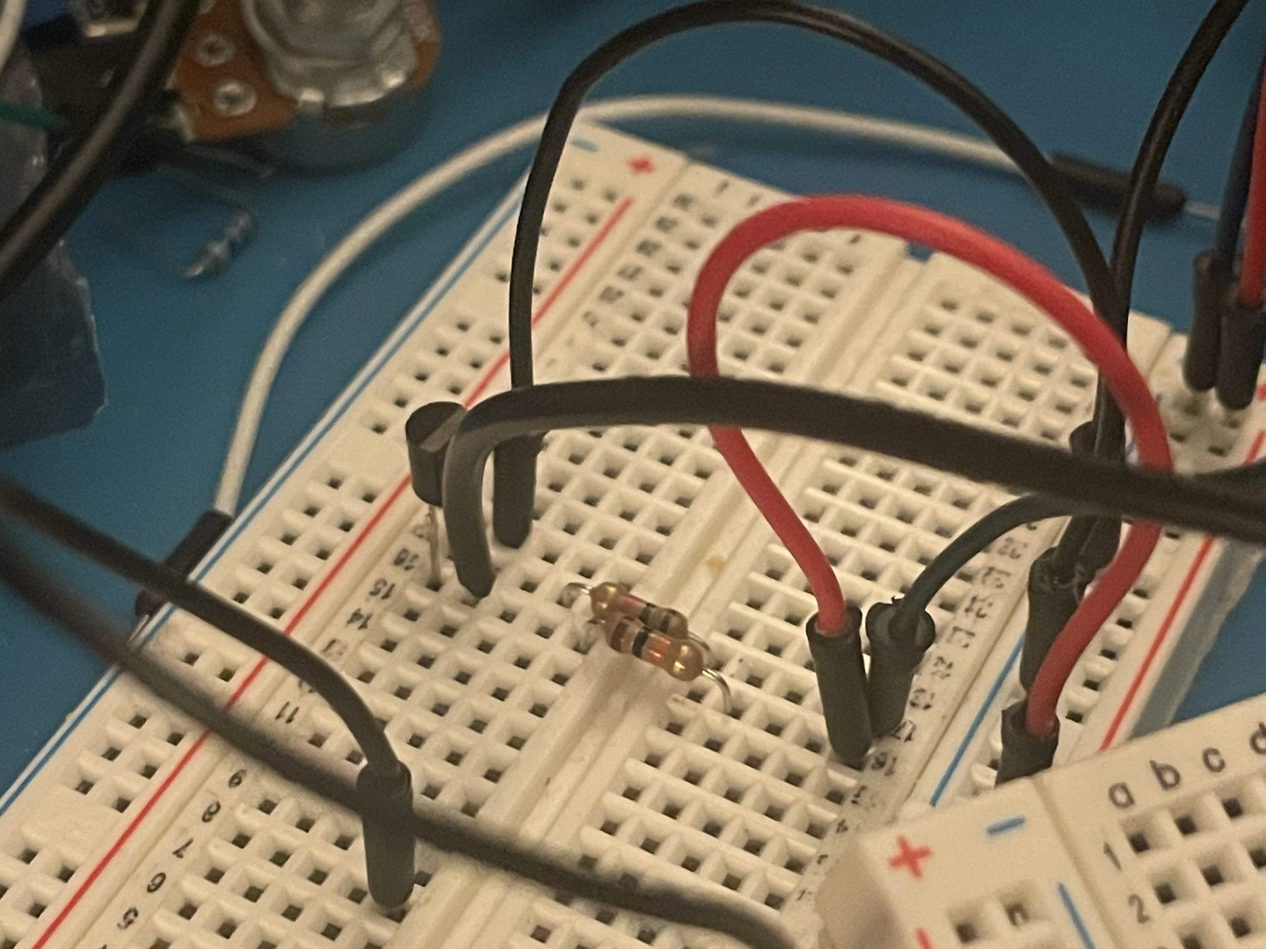
After referencing signals and image quality, it was not good and very distorted always, so I thought I'd give winding a vector yoke a shot. I also experimented with adding blanking by having a 2N3904 reference an assigned blanking pin on the ESP32 that I made in my test program.
2/1/2026:
I had to mentally prepare myself to rewind the yoke. I removed the epoxy by chipping it away and used 28 AWG magnet wire. The rewinding of the yoke is done by unwinding the vertical coil and rewinding it with new wire.
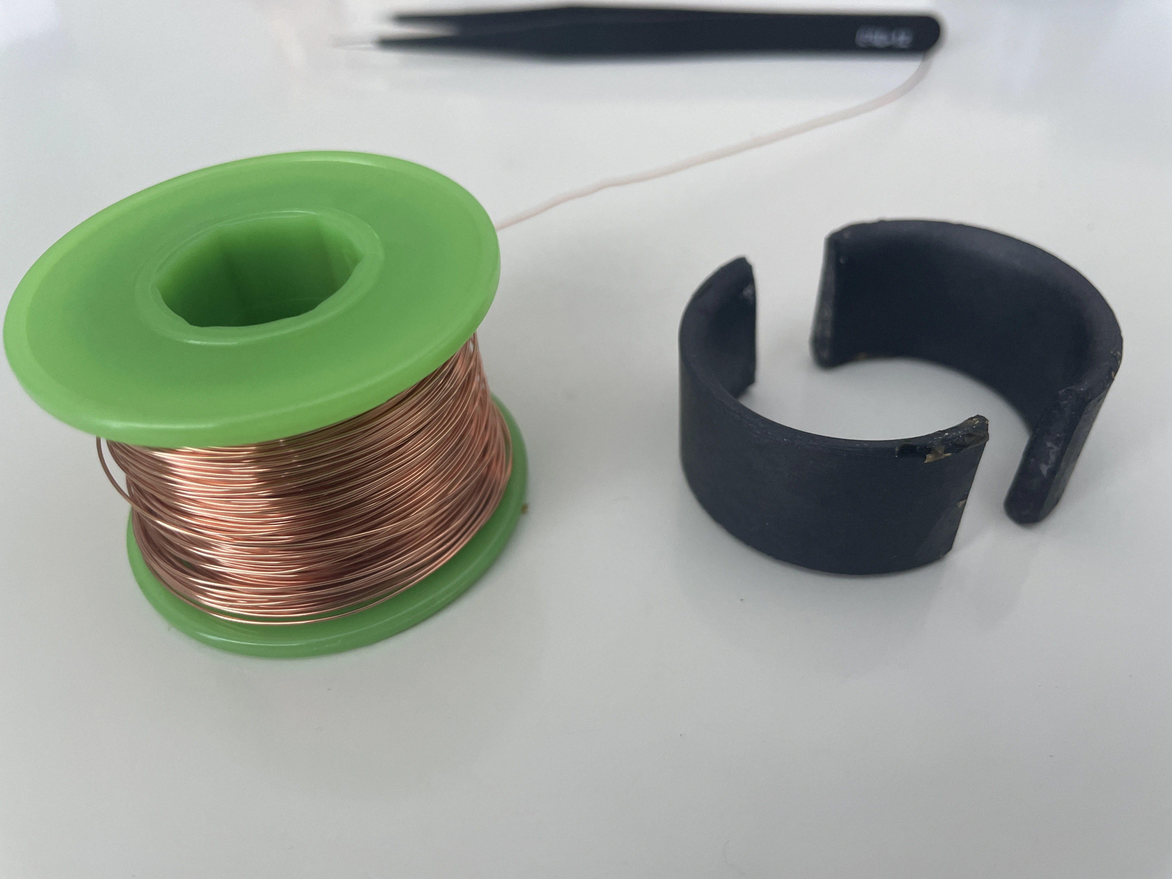
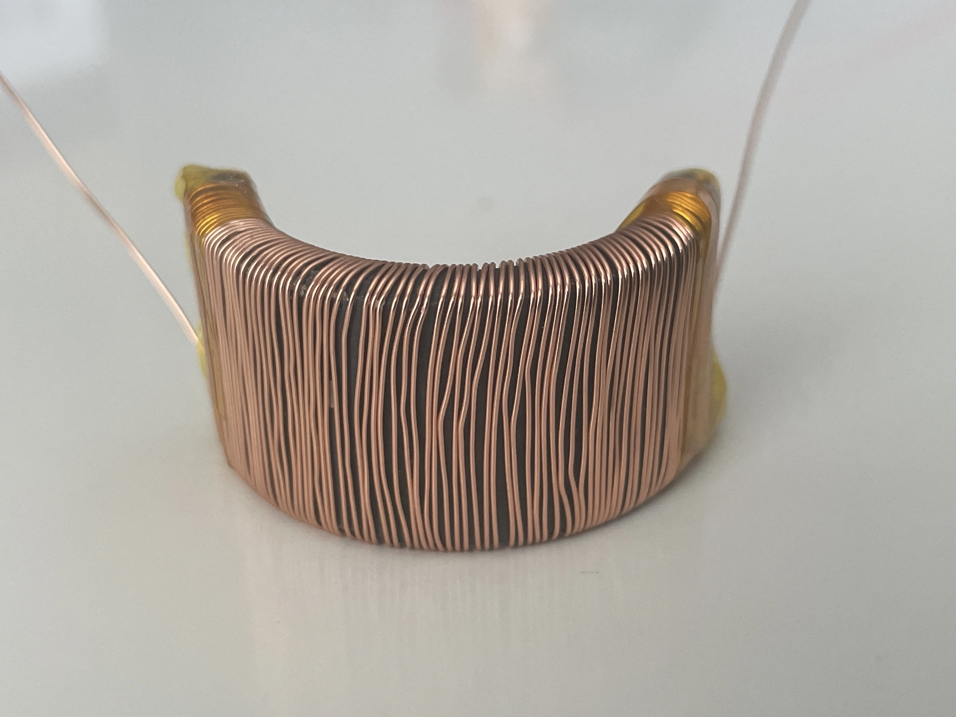
Unfortunately, this didn't work. I think the reason that this did not work was because it was such a small yoke to begin with. It caused the amps to short since the resistance across the new yoke was very little; which was an issue that I figured could happen, but I still gave it a shot.
2/9/2026:
I gave making a larger one a shot to see if I could get any other results. This was off of a necked RF Goldstar 13" set from 1996.
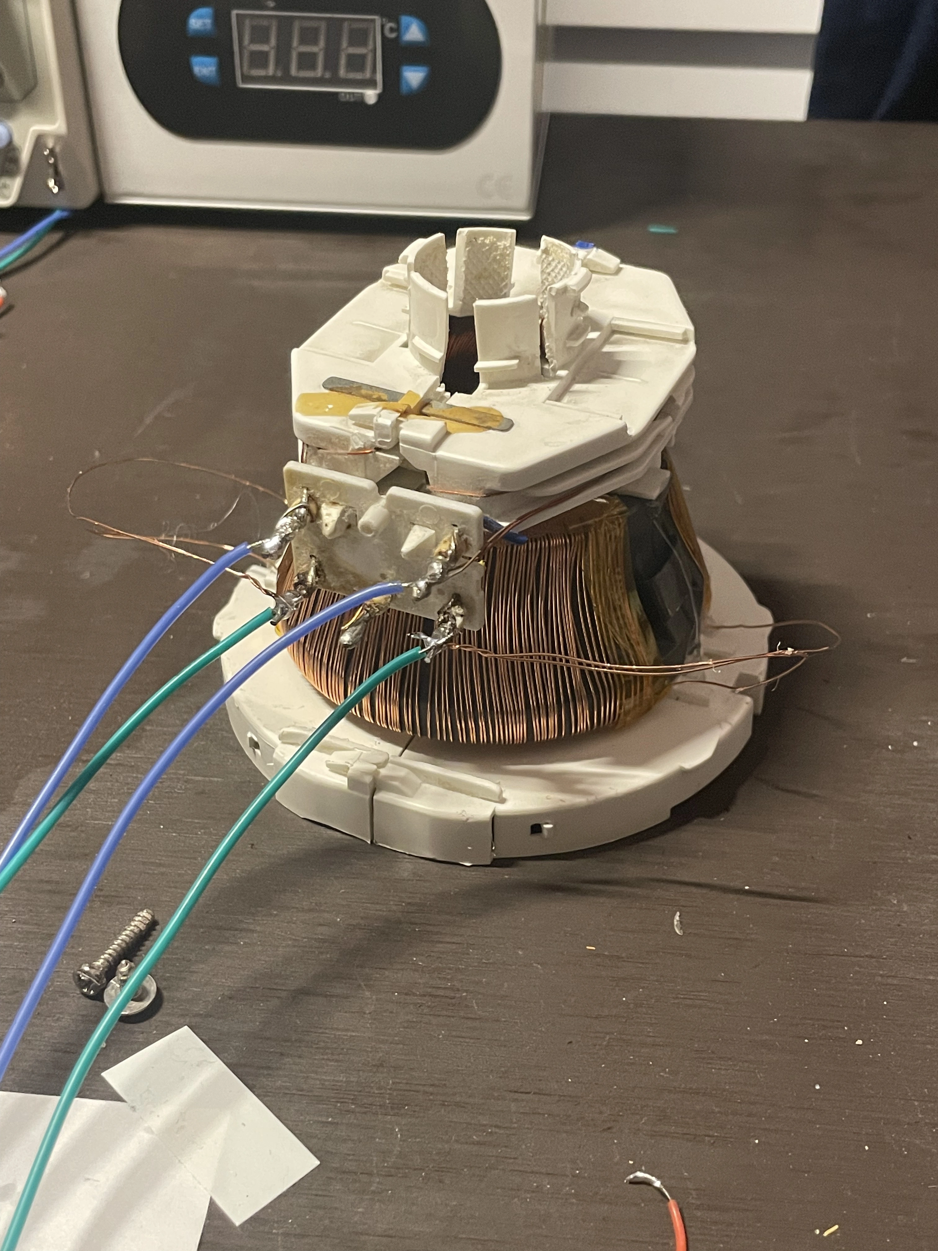
This one ended up working better, but still not that great. (note from 11/4/2026: I think that with my current setup of everything, this yoke would work really well on a CRT, I'll probably give it a shot sometime).
2/10/2026:
I finally got around to putting the custom amplifiers together (one board per axis).
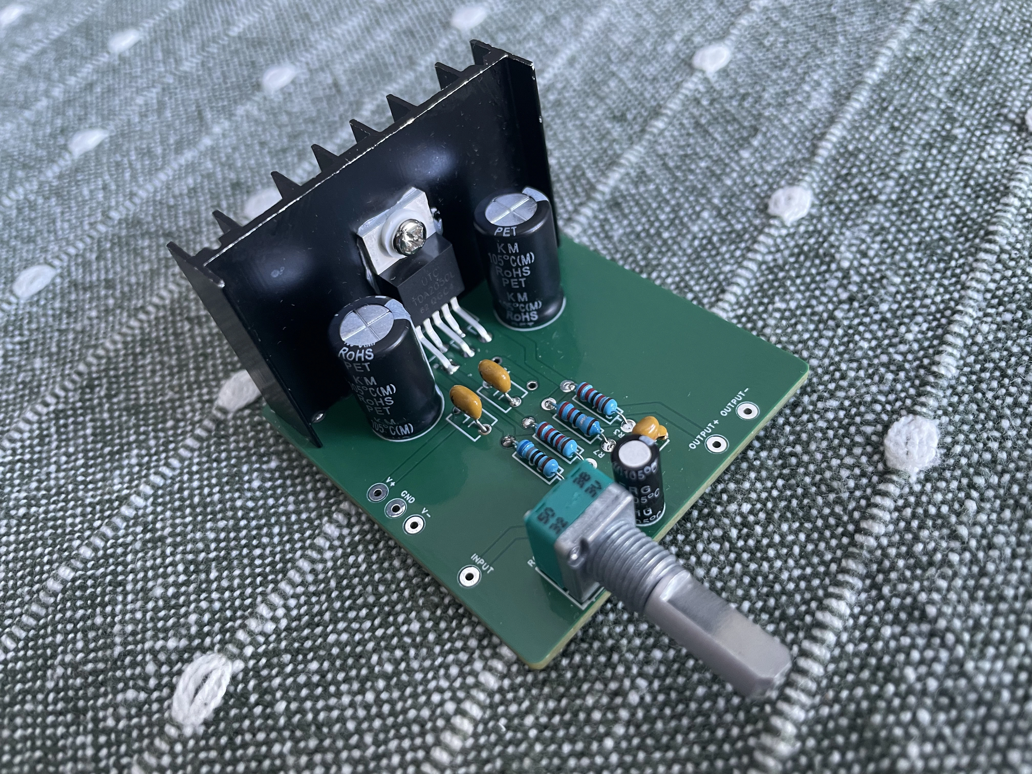
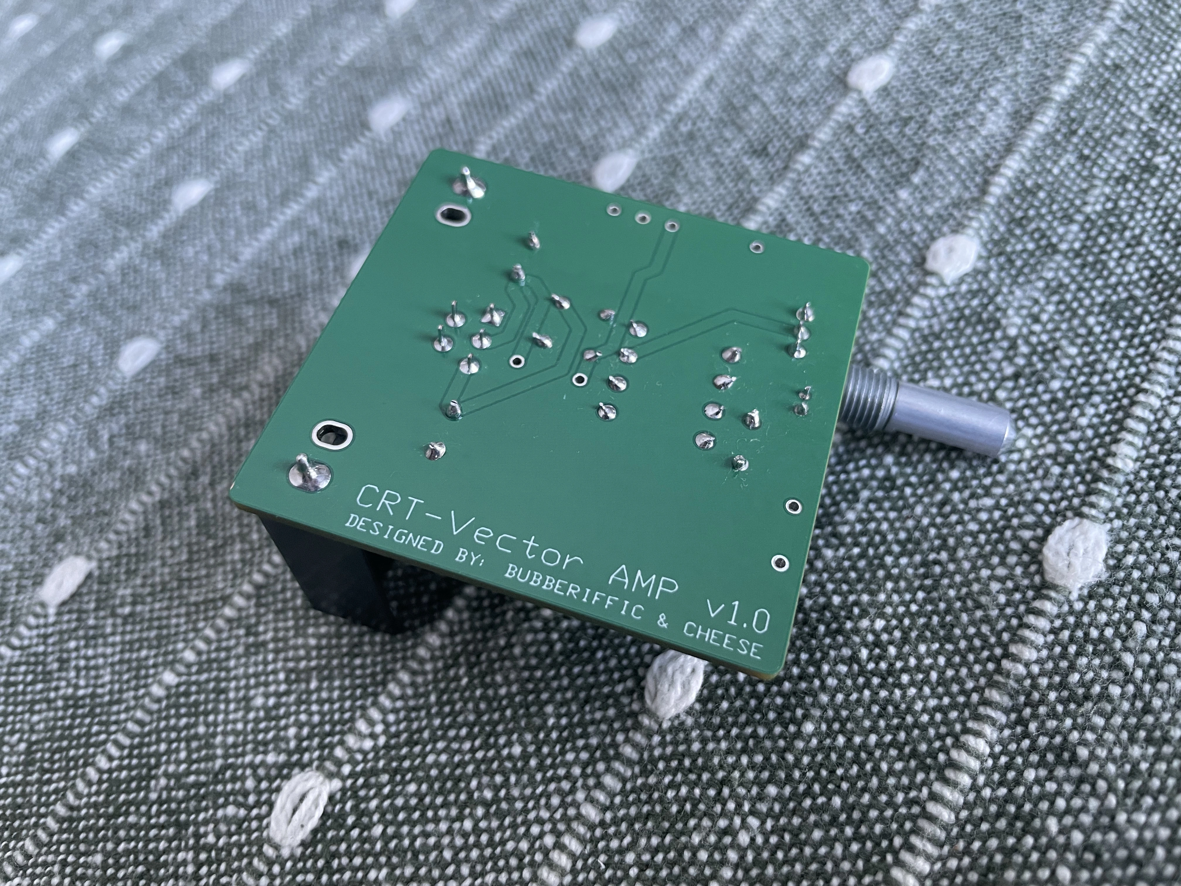
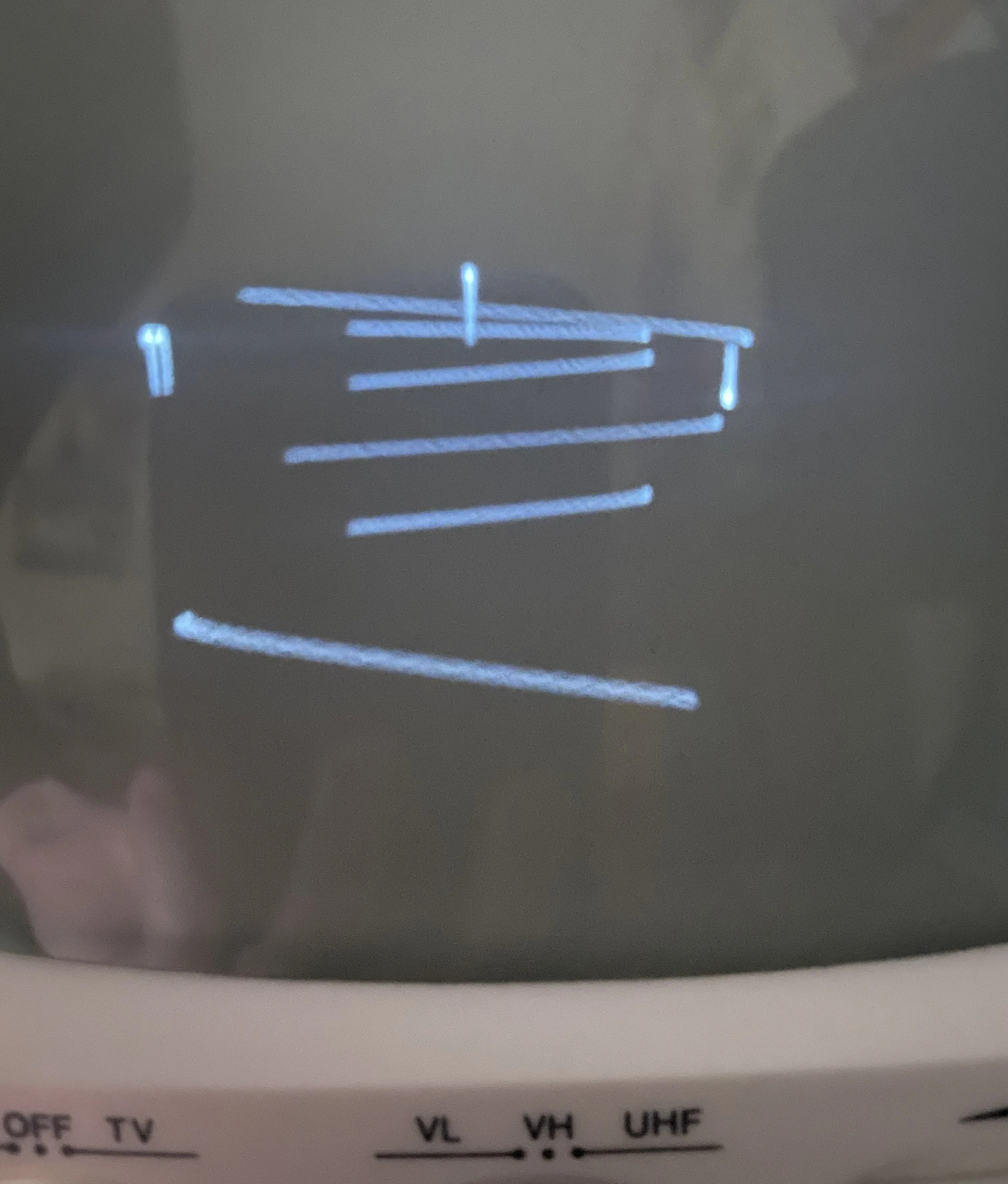
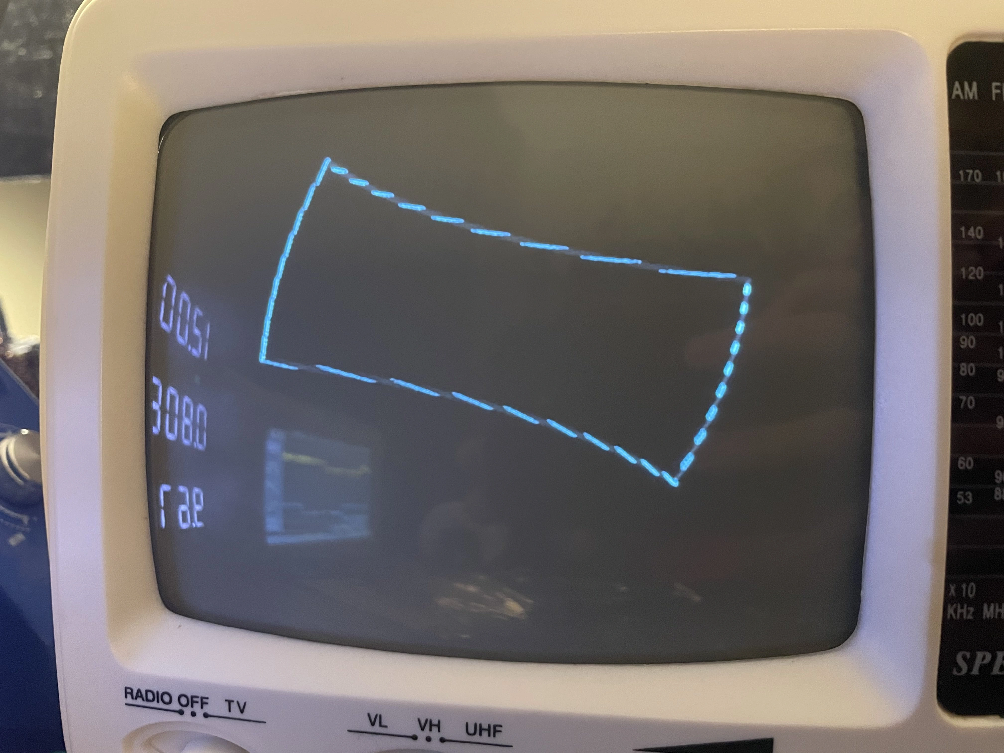
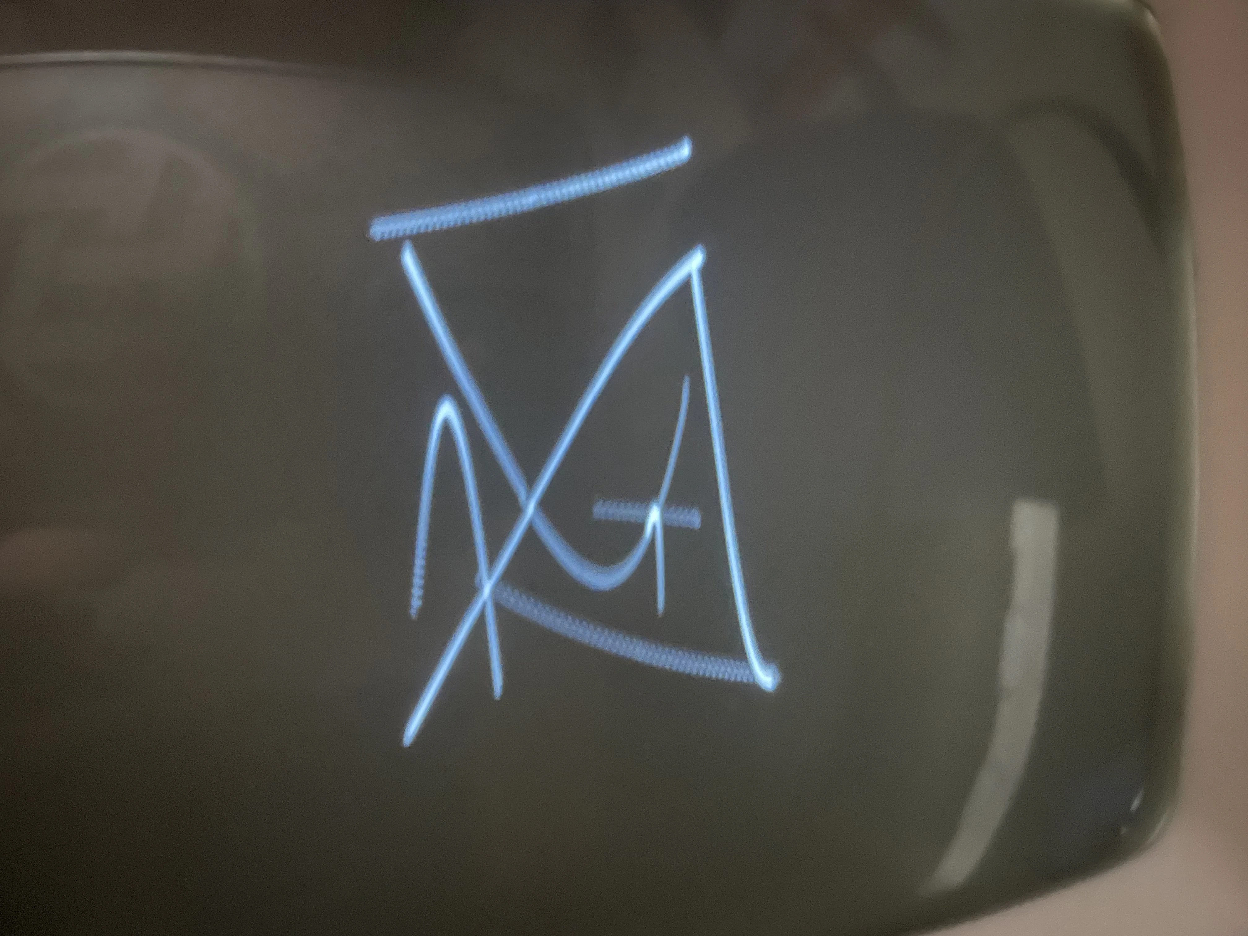
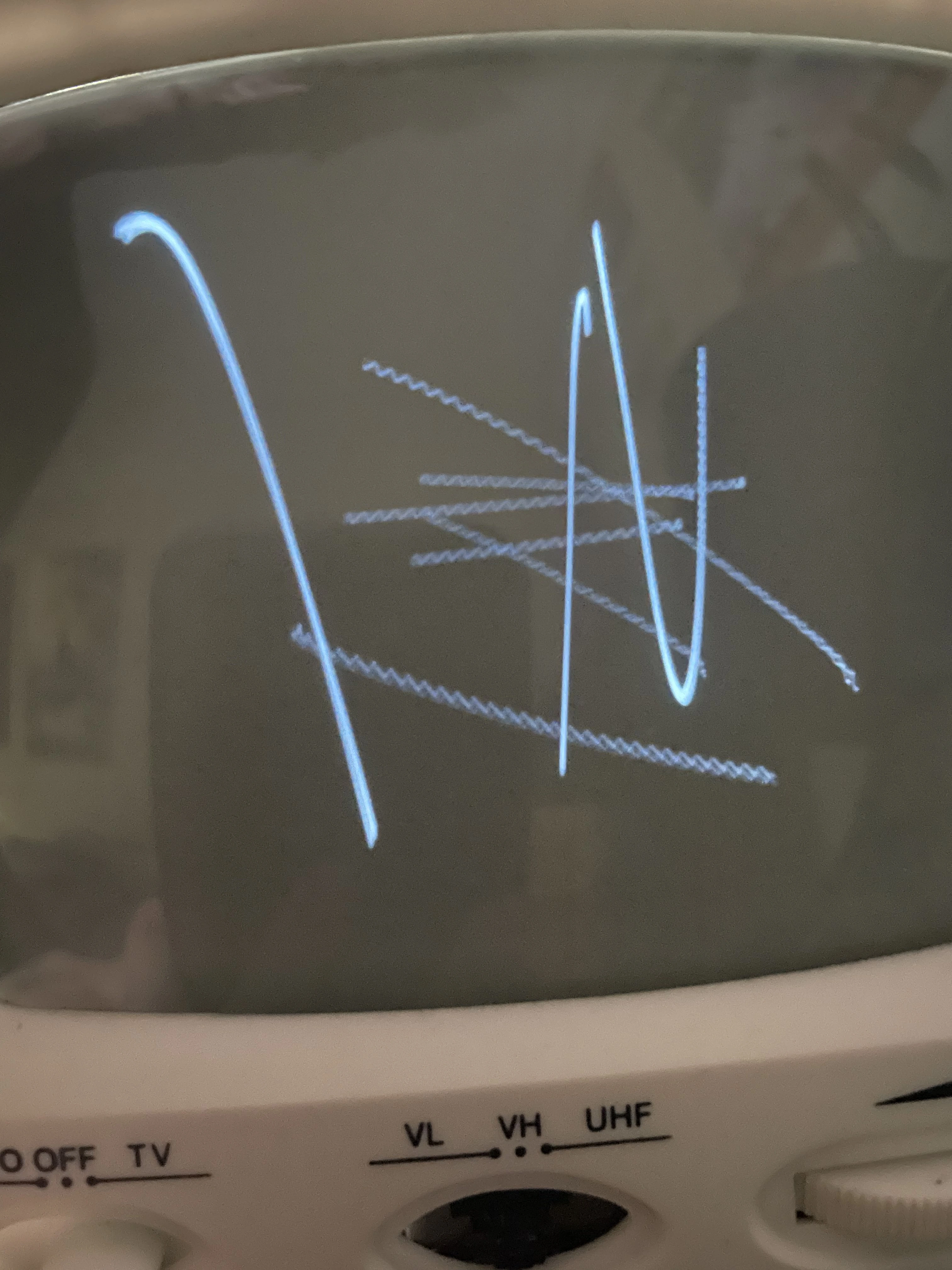
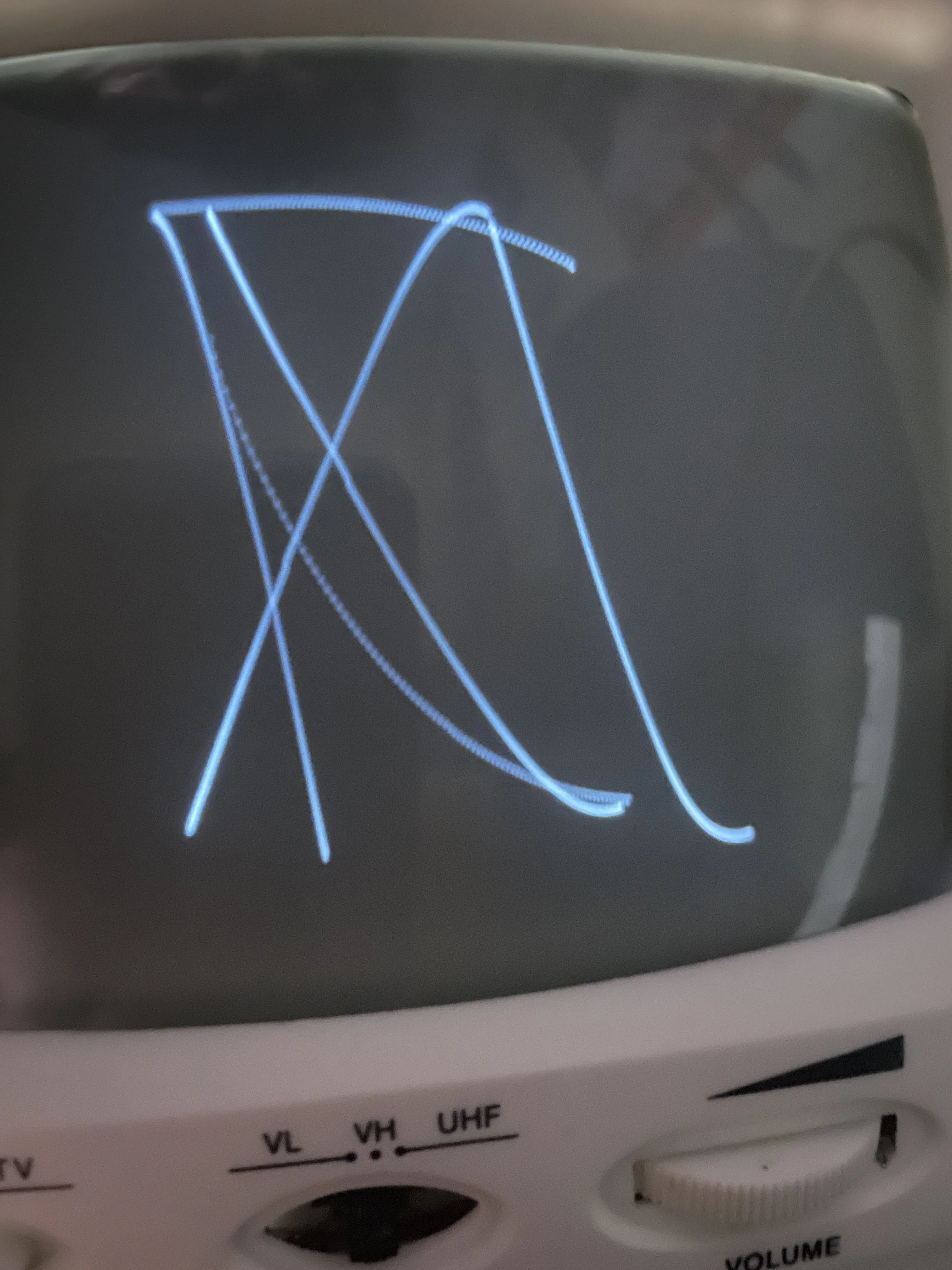
They worked a lot better than the original solutions, but if the beam had to move fast at all (like what it would need to to maintain persistence of vision) the picture would distort. Basically, if the picture was more than a very simple shape, the image would be ruined.
Examples of the distortion effect that I was seeing:
4/4/2026:
I took a break from this project since I was stuck mentally and electronically that this point. I thought that if I ever got it working that reverse-engineering the power supply board would be a good start, so I did.
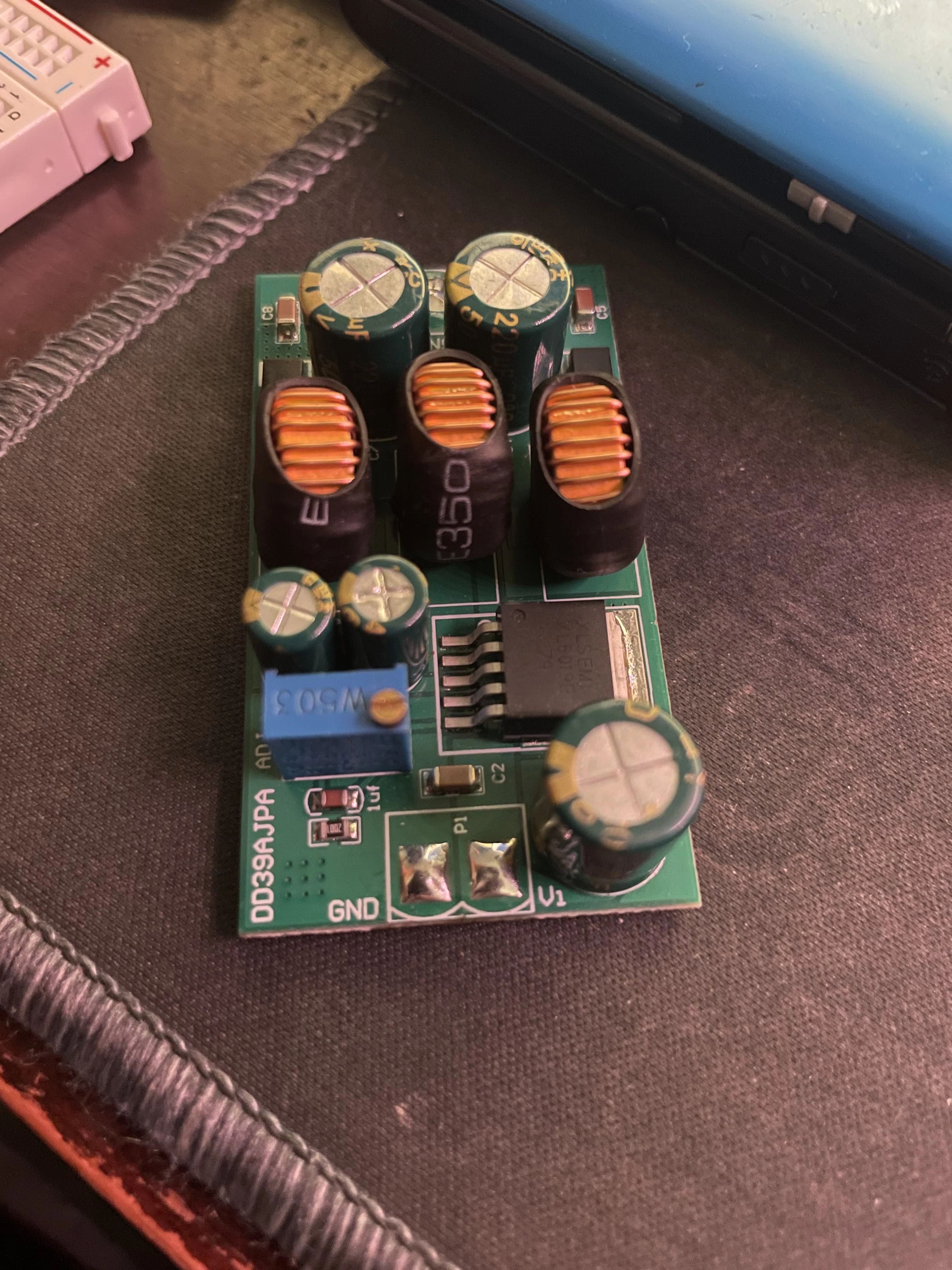
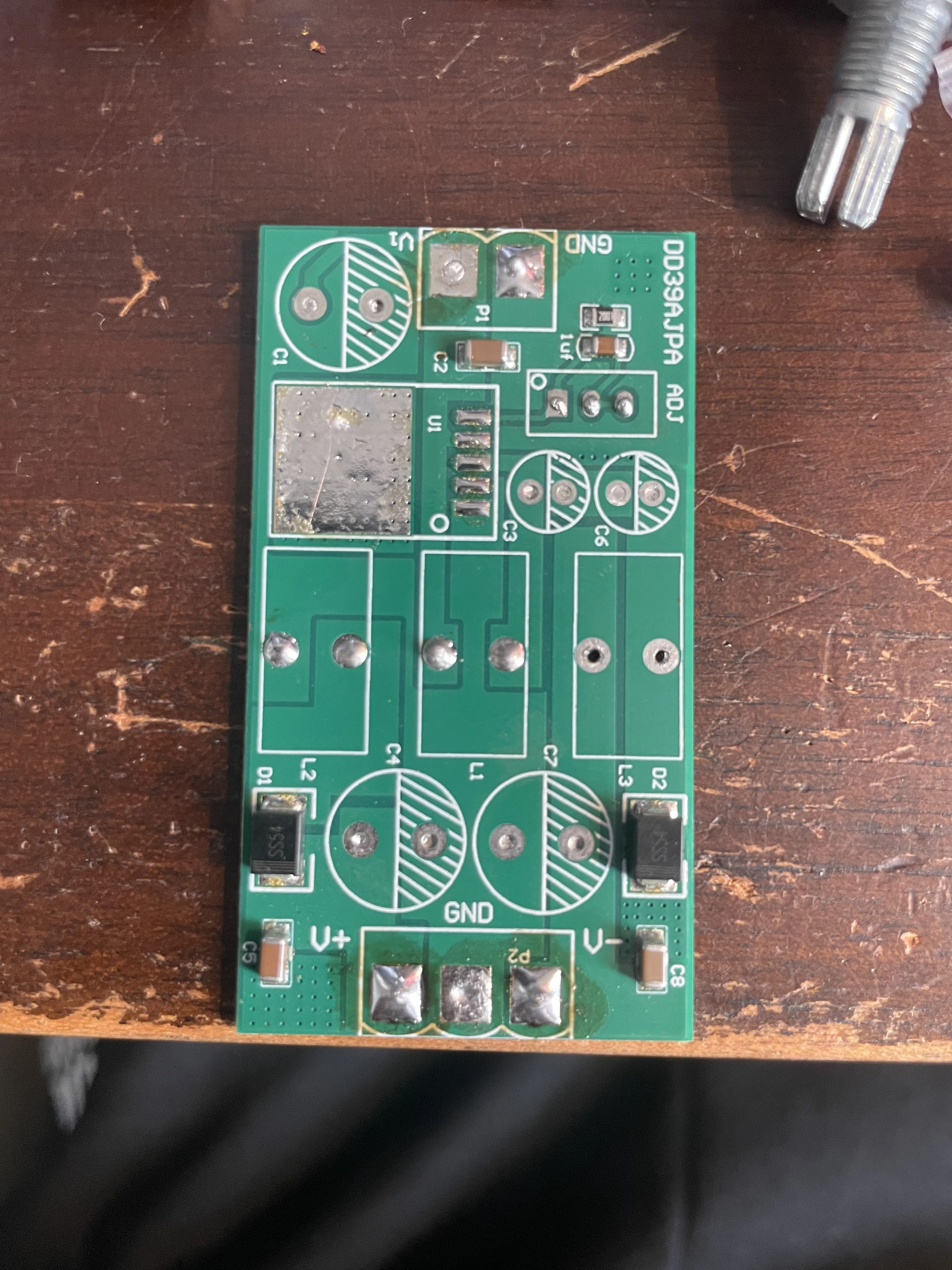
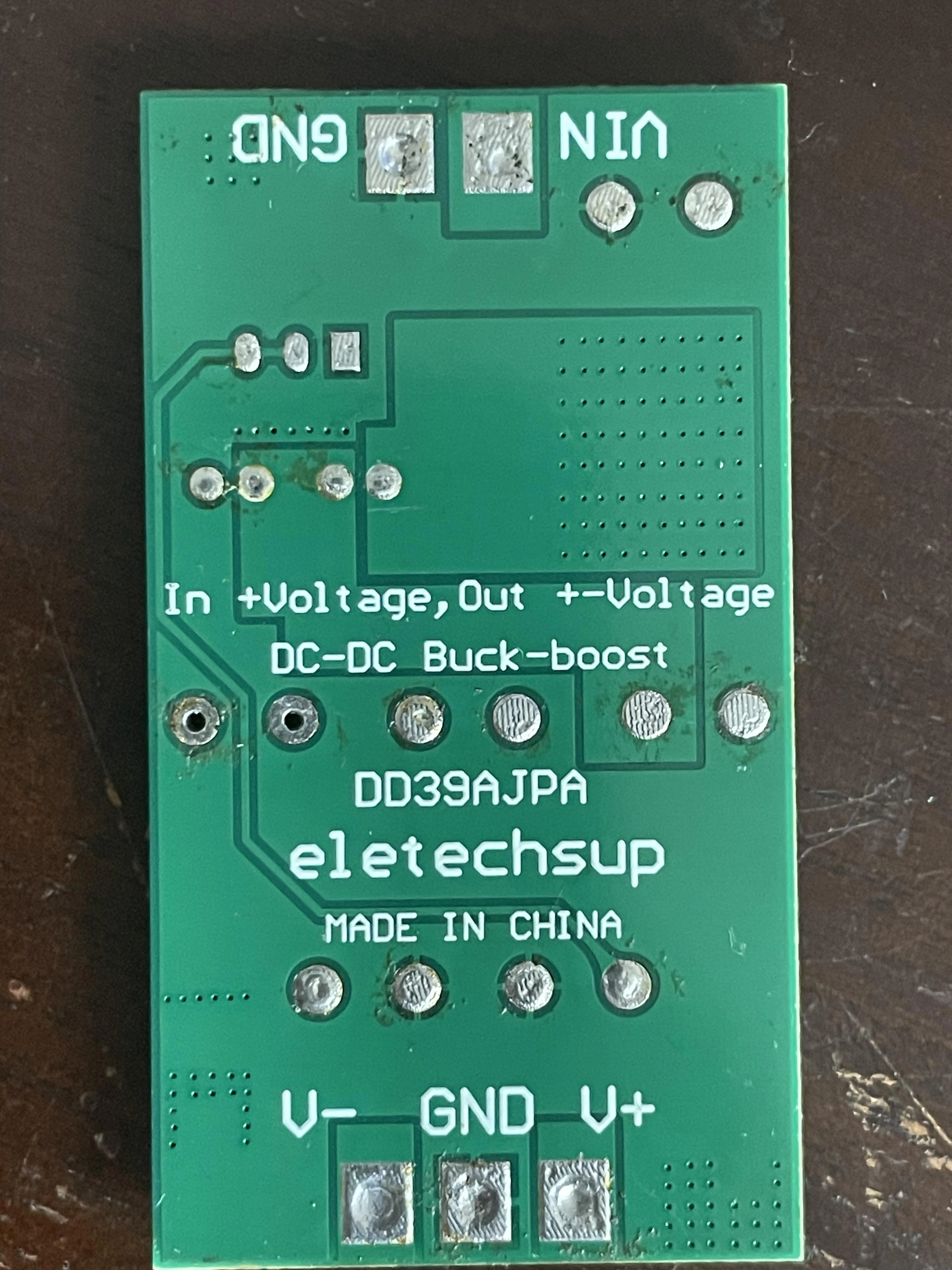
I desoldered all of the components and scanned the board to have as reference when making a schematic. I have not tested if it works or not, but everything should work for the board.
6/5/2026:
While I did build initial "concepts" before this project (there are now images above! there were not images above this when I wrote this originally)... I'm completely starting over with all of the parts and progress on this project, and I'm only starting with the knowledge I've learned from my trial-and-error from the past research I’ve done. Those initial concepts aren't even comparable to anything that will be done on this project, I just thought that I should share that to be transparent!
6/13/2026:
Over the past few days I've been hard at work designing a Vector Amplifier/Deflection PCB to scale up the signal generated by either an authentic Atari Vector PCB or a Micro-Controller with DACs. In the past, I made an AMP that uses the TDA2050 AB-Class Audio Amplifier, which worked to scale the image up on a tube, but introduced lots of noise and such to my understanding.
This time around for the start of this project, I want to use Transistors to amplify the X and Y signals. An online blogger and electronic hobbyist, Jürgen Müller has an open-source XY Deflection Schematic, so I started with that as a base, and then modified it. I designed the PCB on my own as I do for all of my projects. I just sent off the order and ordered all the parts that I should need, so I'm looking forward to when those arrive! The Transistors used are the TIP41C and the TIP42C High-Power Transistor(s).


Introduction:
Around December of 2025 and January of 2026, I fiddled with the idea of creating a Vector CRT similar to the Vectrex. I had a good starting point with custom amplifiers that I made, but they didn't really go anywhere—so I'm starting again here hopefully to finish it! This project was intended to be my submission for the 2026 BitBuilt Summer Competition, but I got stuck with some issues that I thought I should wait on. I've since then added a bunch of progress images from January of 2026, and I plan to continue updates. I'm making lots of progress, so if you're interested, please Like this post!
I really appreciate that I won 3rd place in the 2025 Summer Competition, that seriously means the world! Thanks so much everyone for your support on my previous projects.
1/8/2026:
A CRT TV draws images in a line-by-line format sort of like a printer. That format of drawing images is called a raster image. Old Atari Games and the Vectrex use a vector CRT that only draws images from point to point. This removes the ability of drawing standard video, but allows for really neat glowing lines and bullets in games that can't be found or replicated any other way. A vector monitor works similar to how a Tube oscilloscope works in XY mode. I hijacked the inputs off of the raster yoke (the magnetic pair of inductors that steer the beam in the X and Y direction, one coil for each axis). I bought an audio amplifier pair using the TDA2050 (similar to the amplifiers out of a laser galvanometer).
1/11/2026:
The issue with the current amplifiers are that they are AC-coupled, which doesn't work for drawing vector graphics since sharp corners can get smoothed out from capacitors in the circuit, so I modded the amps for each axis. I also bought a cheap DC-in switching power supply, since the axes work like a 2D coordinate grid, to move the beam negative, the beam needs to be driven with a negative voltage.
You can see the issue with the AC coupling vs. the DC coupling. The yellow channel is the signal out of the ESP32, and the blue signal is out of the amplifier. See the signal corners getting rounded off?
The circuit trying to draw the letter "A".
1/13/2026:
I thought that some of the distortion could be because the yoke was a raster yoke. Basically, a vector yoke has the same inductance and resistance values across both axes, the yoke in a raster CRT usually can't make those quick jumps since the only thing that has to move super fast is the horizontal coil compared to the small movement that the vertical coil makes.
The resistance of the Vertical Coil in ohms.
The inductance of the Horizontal Coil in mH.
I also wired the circuit on prototyping board, which was way better than working with breadboards. Also, breadboards can have stray capacitance, which is not good for vector signal integrity.
1/26/2026:
I redesigned the amplifier boards with the DC-coupling parts with some help from @cheese. Here is the spaghetti-mess of wires that is testing this project.
After referencing signals and image quality, it was not good and very distorted always, so I thought I'd give winding a vector yoke a shot. I also experimented with adding blanking by having a 2N3904 reference an assigned blanking pin on the ESP32 that I made in my test program.
2/1/2026:
I had to mentally prepare myself to rewind the yoke. I removed the epoxy by chipping it away and used 28 AWG magnet wire. The rewinding of the yoke is done by unwinding the vertical coil and rewinding it with new wire.
Unfortunately, this didn't work. I think the reason that this did not work was because it was such a small yoke to begin with. It caused the amps to short since the resistance across the new yoke was very little; which was an issue that I figured could happen, but I still gave it a shot.
2/9/2026:
I gave making a larger one a shot to see if I could get any other results. This was off of a necked RF Goldstar 13" set from 1996.
This one ended up working better, but still not that great. (note from 11/4/2026: I think that with my current setup of everything, this yoke would work really well on a CRT, I'll probably give it a shot sometime).
2/10/2026:
I finally got around to putting the custom amplifiers together (one board per axis).
They worked a lot better than the original solutions, but if the beam had to move fast at all (like what it would need to to maintain persistence of vision) the picture would distort. Basically, if the picture was more than a very simple shape, the image would be ruined.
Examples of the distortion effect that I was seeing:
4/4/2026:
I took a break from this project since I was stuck mentally and electronically that this point. I thought that if I ever got it working that reverse-engineering the power supply board would be a good start, so I did.
I desoldered all of the components and scanned the board to have as reference when making a schematic. I have not tested if it works or not, but everything should work for the board.
6/5/2026:
6/13/2026:
Over the past few days I've been hard at work designing a Vector Amplifier/Deflection PCB to scale up the signal generated by either an authentic Atari Vector PCB or a Micro-Controller with DACs. In the past, I made an AMP that uses the TDA2050 AB-Class Audio Amplifier, which worked to scale the image up on a tube, but introduced lots of noise and such to my understanding.
This time around for the start of this project, I want to use Transistors to amplify the X and Y signals. An online blogger and electronic hobbyist, Jürgen Müller has an open-source XY Deflection Schematic, so I started with that as a base, and then modified it. I designed the PCB on my own as I do for all of my projects. I just sent off the order and ordered all the parts that I should need, so I'm looking forward to when those arrive! The Transistors used are the TIP41C and the TIP42C High-Power Transistor(s).
Last edited: