I'm planning to build a wii ashida with some additional features:
-Video out
-build-in-sensor bar
-relocating bluetooth module (I'm considering WiFi too, but doesn't seem worth it to me)
I wanted to ask if someone could check my shopping list in case I missed something or don't need it. I used the Ashida BOM for reference.
I already have:
-OG GameCube Controller
-Wii sensor Bar (already did some test with the build in infra read LED's)
-Wii family edition with the RVK-CPU-01 (from what I can tell it is perfect for this build, 4-layers etc.)
-128GB micro SD card
As for my shopping list:
-for video out I found the VGA switch by electronic shepherd was recommend in another thread (https://bitbuilt.net/forums/threads/is-video-out-in-a-portable-possible.6634/), is that still the way to go?
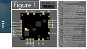
-From 4LayerTech I would order everything that is listed on the BOM

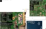
-From Digikey too:
From what I can tell this is everything except for the 10K Potentiometer from mouser, which is out of stock and shipping is very high, is there a good alternative I can order? (preferably EU). This just leaves me with ordering wires (can I just buy any wires with the right awg?) and 21700s.
I'm sorry for the amount of long questions!
-Video out
-build-in-sensor bar
-relocating bluetooth module (I'm considering WiFi too, but doesn't seem worth it to me)
I wanted to ask if someone could check my shopping list in case I missed something or don't need it. I used the Ashida BOM for reference.
I already have:
-OG GameCube Controller
-Wii sensor Bar (already did some test with the build in infra read LED's)
-Wii family edition with the RVK-CPU-01 (from what I can tell it is perfect for this build, 4-layers etc.)
-128GB micro SD card
As for my shopping list:
-for video out I found the VGA switch by electronic shepherd was recommend in another thread (https://bitbuilt.net/forums/threads/is-video-out-in-a-portable-possible.6634/), is that still the way to go?
-From 4LayerTech I would order everything that is listed on the BOM
-From Digikey too:
From what I can tell this is everything except for the 10K Potentiometer from mouser, which is out of stock and shipping is very high, is there a good alternative I can order? (preferably EU). This just leaves me with ordering wires (can I just buy any wires with the right awg?) and 21700s.
I'm sorry for the amount of long questions!
Last edited: