Well guys, there's some good news, and there's some pretty bad news.
Good news:
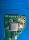
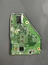
I got VGA up and running. Wasn't too hard, just had to re-run the installer and wire it up. Booted up some Super Mario Bros. Wii and the video looked amazing.
View attachment 41393
Bad News:
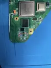
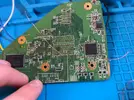
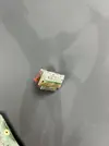
I was so close to finishing. Just had to take out the batteries so I could solder up the speaker wires, then put them back in and close it up. Too easy I guess. Unfortunately, when taking out one of the batteries, I got the dreaded magic smoke. I believe the issue to be: the paper ring separating the outer negative casing of the li-ion to the positive terminal came off and shorted together on the same line. The heat was so much that the wire connecting the battery tab to the pms came loose.
View attachment 41394The console was off and I took it out as fast as I could. I didn't know what to do next, so I measured some resistances, and put the one leftover battery back in. I was freaking out trying to make sure nothing was fried. I wanted to see if it still booted. I figured the voltage wasn't high enough, so I also inserted the charger.
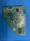
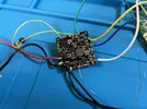
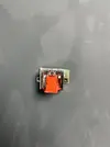
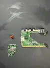
This is where the second problem came on. While trying discern what the issue was, the GC +2 area of the ashida started smoking. To be honest, I don't know if it was specifically the GC +2 or something around that area, but smoke was coming from there. So I quickly took out the battery and the charger. The Gnd wire connecting the Wii to the 4LT controller breakout board got so hot I believe it disconnected from both sides
View attachment 41395
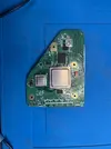
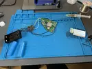
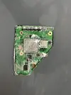
I believe any of these three problems could've made the ashida smoke twice: Paper ring knocked loose and + and - shorting on the same line for the first issue, Measuring voltages while the charger is connected like a dummy(Cannot remember exactly if I did this, but this could've been the issue) for the second issue, or the simple high output of the charger Im using(for the second issue). It's a 96W Mac charger. I thought the PMS PD 3 was compatible with all chargers so Ive just been using USB C PD that Ive been using for my pinecil. And I have been charging the ashida like this for a while, while testing.
Troubleshooting:
I've measured the Resistances of every line, and the all read what they should normally read(3.3v is reading 1.3k but I figure this is high enough). However when 3.3v and gnd are connected to the 4LT controller breakout board, 3.3v and Gnd on the Wii are shorted together.
Voltages also read what they should, all within their normal readings.
Man, its hard going from such a high to such a low. I feel pretty dumb right about now. I really hope this project is salvageable.

")