Guide The definitive Wii trimming guide is live!

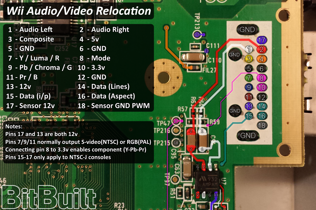
@ShockSlayer on the audio video relocation picture, it says pins 15-17 are for ntsc-j consoles, but how its labeled in the picture, it should be pins 14-16
av_port.png
 
Is it important that the U10 relocation wire follows the exact path shown in the guide? I just did mine and realized I laid it across the middle of the GPU.
 
Is it important that the U10 relocation wire follows the exact path shown in the guide? I just did mine and realized I laid it across the middle of the GPU.
No, it doesn't matter
 
What exactly is a NTSC-J console? Google and Wikipedia didn't help very much.
 
I noticed that the components that keep the MX chip from overdrawing get power from the battery, which is 3v. Do I still need to give that power, or will I be fine without them? And if I do need to power them, can I use the 3.3v from my regulators instead?
 
I noticed that the components that keep the MX chip from overdrawing get power from the battery, which is 3v. Do I still need to give that power, or will I be fine without them? And if I do need to power them, can I use the 3.3v from my regulators instead?
No, if you aren't wiring the 3v CMOS battery just leave it be. Custom regs only supply power when turned on, so when you turn the system off the clock will reset anyway. You need the CMOS battery to keep the clock running when the system is turned off, but it's not essential for anything except Animal Crossing.
 
Hi everyone. I accidentally took off the ESD components in the signal path of my composite video on my Wii. Can anyone tell me what the values of those are? It's those highlighted in blue in this picture. I think based on the silkscreen it's capacitor C92, Inductor bead FIL20 and there's a third component which is either unlabeled or is signified by V4. This is weird because that component on other Wii mobos seems to be C93, another capacitor, and it certainly looks like a cap or a resistor. I sort of think that "V1-4" is just a designation for "Video" output, and they simply omitted the second capacitor code, but I maybe I'm wrong?

Also, I don't currently have any of those inductors lying around, because why would I, so I'm wondering if maybe I should just totally bypass that stuff with a bodge. Although I don't want to create any noise in my system.

Thanks


o9hXA7A.png
 
The V1-4 components are varistors, they will clamp the video output if the voltage goes too high. You can just bypass those components as long as you still have the big cap. If you're putting this in a portable you can just bypass everything as long as the video wire is shielded or twisted with ground.
 
You can just bypass those components as long as you still have the big cap.

Thanks for the reply. I should still have the big cap. (I'm assuming you mean C90, the 100uf cap in the photo)
I didn't remove anything except for those three small components.
 
The similar looking one on the composite line, as long as that is there you can just grab your video anywhere past that

!

Ah, I see. It's C91, the first of that group. I definitely didn't mess with any of those.

Thanks again!
 
Back
Top