
You are using an out of date browser. It may not display this or other websites correctly.
You should upgrade or use an alternative browser.
You should upgrade or use an alternative browser.
Worklog RIIIIIP
- Thread starter The_Smeags
- Start date

- Joined
- Aug 2, 2016
- Messages
- 294
- Likes
- 146
- Joined
- Aug 2, 2016
- Messages
- 294
- Likes
- 146
sure will, i still have to cut that top left corner some more in order to allow the usb ports to fit anyways lol
- Joined
- Aug 2, 2016
- Messages
- 294
- Likes
- 146
relocated the bluetooth module, using continuity, it makes contact, no bridges. once i can test the voltages ill be wiring up av too.


Looks good!
- Joined
- Aug 2, 2016
- Messages
- 294
- Likes
- 146
thanks man, i was a little worried at first, but then i figured i'd scratch the traces at different sections since it couldn't bridge if they weren't together.Looks good!
might be able to shorten the data wires a lot more, i also used 22awg solid core wire for 5v and 12v. will swap it (probably) with stranded wire. is 22awg ok? would've used 18awg on those two like i did with the other places, but didn't think it was necessary (plus i couldn't actually use that thick of wire on any 12v pins lol)
Nice find for placement, I may have to copy that in mine... Can't wait to see it finished!
22awg should be fine, the processor/gpu/ldo combo are the only parts that really need thicker wires since they can draw some amps, while the rest of the components stay quite low, usually in the milliamps range.
22awg should be fine, the processor/gpu/ldo combo are the only parts that really need thicker wires since they can draw some amps, while the rest of the components stay quite low, usually in the milliamps range.
- Joined
- Aug 2, 2016
- Messages
- 294
- Likes
- 146
haha go for it, i might have to push mine a little further back, if it gets in the way of the batteries, i simply tossed it on my board and noticed it sat nice next to the nand (the chip i want to say) glad to hear that, ill do my best to make this project work out, really lovin' the wii for what it can do.Nice find for placement, I may have to copy that in mine... Can't wait to see it finished!
22awg should be fine, the processor/gpu/ldo combo are the only parts that really need thicker wires since they can draw some amps, while the rest of the components stay quite low, usually in the milliamps range.
- Joined
- Aug 2, 2016
- Messages
- 294
- Likes
- 146
Ordering some stuff today. Probably going with regulators and screen and maybe tacts and sliders? Have to order a case for my n64 mini.
- Joined
- Aug 2, 2016
- Messages
- 294
- Likes
- 146
Have a lot of stuff on its way.
Aside from that i wired up av out, the usbs, as well as shortned the data wires on the bluetooth module. Something i was curious about was, on the guide, av has a few data lines. So do i have to do anything wit those? Ill have some pics up tomorrow
Aside from that i wired up av out, the usbs, as well as shortned the data wires on the bluetooth module. Something i was curious about was, on the guide, av has a few data lines. So do i have to do anything wit those? Ill have some pics up tomorrow
Nope, that's for Japanese TVsav has a few data lines. So do i have to do anything wit those?
- Joined
- Aug 2, 2016
- Messages
- 294
- Likes
- 146
Thanks. I have to get my board running before i make any serious progress which i hope to do so today.Looks pretty good! I hope to start a Wii Portable soon. I just finished my Gamecube Portable.
Nice, compared to the gc, the wii isnt as tedious to work with, but its interesting for sure. Good luck
Josiah
"has done nothing for this community"
- Joined
- Jul 19, 2016
- Messages
- 0
- Likes
- 0
- Portables
- 0.000000001
Thank you. Hope you get that board running soon!Thanks. I have to get my board running before i make any serious progress which i hope to do so today.
Nice, compared to the gc, the wii isnt as tedious to work with, but its interesting for sure. Good luck
- Joined
- Aug 2, 2016
- Messages
- 294
- Likes
- 146
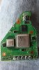
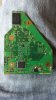
Couldnt get the last board to run. Trimmed this new board, had it boot portablizemii. (before trim) Will do u10 relocation soon. This time i wont wire up bluetooth until confirmed booting board. Next week when i get paid ill be ordering some ti regs and maybe some batteries. By then i can finally finish the n64 mini and hopefully will recieve the stuff to assemble the front.
Attachments
- Joined
- Feb 25, 2016
- Messages
- 1,465
- Likes
- 3,020
Lookin good dude. Here's a tip: relocate u10 before trimming so there is less to troubleshoot if it doesn't work right away after trimming. I usually like testing the custom regulators on the wii before trimming too.
- Joined
- Aug 2, 2016
- Messages
- 294
- Likes
- 146
I hear you. But i couldnt remove u10 with heating so i just remove the section off with a dremel..i also dont have a way of testing the voltages so im currently forced to do it this way which is a pain.Lookin good dude. Here's a tip: relocate u10 before trimming so there is less to troubleshoot if it doesn't work right away after trimming. I usually like testing the custom regulators on the wii before trimming too.
I got some 3ds sliders so i can at least fiddle with my controller lol. Ill have more stuff posted tonight
- Joined
- Aug 2, 2016
- Messages
- 294
- Likes
- 146
Was wiring up av. A lot of the pins have continuity with all of the pins on the encoder. What does that mean, shorts? Bridges?
Similar threads
- Replies
- 0
- Views
- 1K
- Replies
- 2
- Views
- 455