Question My Ashida OMGWTF Trim Won't Boot

Joined
Feb 3, 2025
Messages
16
Likes
0
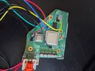
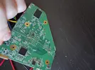
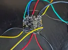
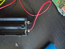
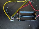
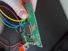
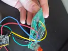
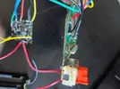
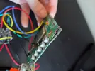
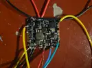
Im having trouble getting this to boot idk what I did wrong. I follow the YouTuber Dubensinhower the one who did a tutorial and I hooked up everything he did except I kept my av cable port on my motherboard to test to make it easier and then if it worked I would trim the rest off. But I can't get it to appear on the TV but I feel some heat from the smaller silver square but not really any from the big silver square. Here is a picture and hopefully you can tell me what I did wrong. But also when the first time I tested I used 1 battery and I did feel static from the battery when I was pulling out and I noticed some wires came off when trying to test it. So idk if i short circuited the pms and the wii or just 1 of them. So please tell me what I can do to make this boot.
341.webp
 
Hey @YT N9-Volt,I will say that you really need to clean UP your wii with IPA,at least for get off the marker and especially the flux around the 1.8V regulator that you put off.It's basic but sometimes it can make a trimm working.Also,did you follow the wii trimm guide ln the bitbuilt guide hub?It's really helpful because dubesinhower don't say all in his video even if it is really complete.I recommend you to check this one of GingerOfOz
Also have you sand the edges with differents weight?(From the lowest to the highest).
It's a lot lf thing I know but it helps a lot in some cases :)


Others helpful links:
https://bitbuilt.net/forums/threads/the-definitive-wii-trimming-guide.198/

https://manuals.bitbuilt.net/guide/category/Wii
 
Last edited:
It looks like you didn't relocate U10 to U5, which is why the GPU (the bigger silver square) isn't heating up and thus outputting no video. The Definitive Wii Trimming Guide tells you exactly how to do this relocation. You also didn't wire up 1v to the Wii, which will also prevent it from booting. I would agree with @randomguy to clean up the board with some isopropyl alcohol and make sure to sand thoroughly, as leaving marker and flux residue and bits of copper hanging off the edges can lead to shorts. Check resistances between voltages and ground before attempting to boot to ensure no shorts. Some voltages will have low resistances to ground (<50 Ohms) like 1.8v, but others like 3.3v should have resistances in the thousands.

Best of luck putting together your Ashida!
 
I cleaned it up and I did i found out that i did forget to wire the 1 volt and I already did sand it before I posted on here from 80 grit to 800 grit I just didn't sand the outer motherboard part where I didn't trim since that should be fine. But I did the relocation I removed the regulator and I wired the wire to the chip which is the little hole to the pms 2 and which is the most annoying thing to get the wire in I had trouble getting that in and I don't even know if it's pushed in all the way and I tried pushing it in all the way I could for hours even with pliers but it would just bend when I put it in and I used 34 guage magnet copper wire. I don't know what's going on so here's pictures. Still no AV output.
 

Attachments

  • 20251107_102429.webp
    20251107_102429.webp
    404 KB · Views: 39
  • 20251107_102442.webp
    20251107_102442.webp
    573.6 KB · Views: 42
  • 20251107_102455.webp
    20251107_102455.webp
    847.7 KB · Views: 37
  • 20251107_102502.webp
    20251107_102502.webp
    1.8 MB · Views: 41
  • 20251107_102506.webp
    20251107_102506.webp
    1.4 MB · Views: 44
  • 20251107_102523.webp
    20251107_102523.webp
    389.1 KB · Views: 34
  • 20251107_102533.webp
    20251107_102533.webp
    262.2 KB · Views: 42
  • 20251107_102540.webp
    20251107_102540.webp
    519.4 KB · Views: 39
  • 20251107_102549.webp
    20251107_102549.webp
    399 KB · Views: 40
I also did some resistance checking but the next one for the ground 1.8 volt was some reason like 0.02 which i don't know why but I tried using either 20k V or 200 V for my red Gardner manual multimeter from Menards. But I never used a multimeter before.
 

Attachments

  • Screenshot_20251107_104857_OneDrive.webp
    Screenshot_20251107_104857_OneDrive.webp
    57.5 KB · Views: 39
Also both silver squares are heating up and the pms is hot as well so idk what's the issue.
 
Hey again,please don't triple post like that,you can still edit the message,it's more practical.For your Wii,I will say that you really need to clean your solder joints,not with IPA because you already did it but you need to don't have wires exposed like it is on pictures.Actually,you can have shorts between the pms components for the pms and even (sometimes)the "magic" smoke.Also make sure to remove the capacitors on the right of the Wii,they aren't helpful anymore if you use a pms.Hope it helps:)

Edit:Also,you say that you don't have any AV outut but I don't see any cables for this,no ones for YPRBR or Composite like this should look(here is an example)
Cap.webp
 
Last edited:
But the av port is on the board so I should be getting a signal because they only do this if the av port is removed because how would I do it if the port isn't removed? Dubinsenhower uses a loose composite cable to attach at the bottom of the port but I can't since the pins are in the board.
 
It's impossible to diagnose the problem with your wiring the way it is. You have too much exposed wire with stray strands pointing out all which ways that could have caused a death short, and your U10 via joint is a boulder that is probably touching other vias.

You need to disconnect the cells, desolder everything, clean the boards with IPA and a toothbrush, and redo the wiring slowly and carefully. By the looks of it your biggest problems are cold joints and no flux, so I'd raise your iron temp by 30 degrees C and grab some MG Chemicals 8341 flux paste from Amazon. It'll make a world of difference.

Just make sure that before you redo the wiring on the Wii, that you just wire in the cells and a power button and check with a multimeter that the PMS is outputting all the correct voltages. For voltage checking you should set your multimeter to 20v, and for resistance checking you want 2k or 20k ohms (Ω symbol) depending on which gives you a reading in whole numbers. The cells much be disconnected before you probe, and any resistance reading lower than 10 ohms indicates a short. For voltage readings the PMS must be powered and turned on, and you must only probe one voltage rail at a time with the black probe always on a GND pad. You cannot measure voltage across rails like you can measure resistance between rails, if you try it the PMS will probably die.
For the U10 do you mean the regulator area or putting in the wire in the dot with the solder on it? Also by the wires exposed do you mean by the wires are too long with the plastic covering off or they are not twisted and tinned enough? Yeah i haven't put flux on them and i do have some in a little container that i could try doing. I don't got a temperature controlled soldering iron which I'm hoping that i don't need one. I can try cleaning it again as well. So I need to check voltage with the pms 2 with batteries and holding the button to power it while having the multimeter black probe touching ground on the pms 2 and the resistance checking is on the wii not the pms 2 right? No batteries for resistance checking right because i did not use batteries for resistance checking on the wii?
 
  1. The little dot on the Wii. That big old blob is probably touching another pad, and even if it isn't it will eventually rip the U10 via out of the board.
  2. There's too much plastic jacketing removed. For safety, however long/deep the pad that you're soldering to is, is how much metal you should be exposing. 2-4mm usually. You don't need to twist the wires, just apply solder to the wire directly to saturate it and then mate that with the pad (which should also have a bit of solder applied so the two join readily. And you don't want plain rosin flux from a container, that shit just burns and doesn't help much. You want a pen/dropper/syringe of flux mix like Kester-951 or MG-8341.
  3. Get a temp controlled soldering iron, it's basically required for stuff like this. The Pinecil is the current recommended iron for beginners. It's small and cheap, but very capable with the new tech. Get a cheap solder sponge and a little tin of Tip Tinner powder as well. It'll make using it easier and extend the life of the tips buy a lot.
  4. Correct. Check the PMS output voltage with the batteries in, check the Wii resistances with the PMS disconnected (having the PMS wired to the Wii will mess with the resistance chart). You don't have to hold the power button down though, just press once to turn the outputs on.
What do I touch with the red probe when testing the voltage on the pms 2 to check if its outfitting voltage right?
 
  1. The little dot on the Wii. That big old blob is probably touching another pad, and even if it isn't it will eventually rip the U10 via out of the board.
  2. There's too much plastic jacketing removed. For safety, however long/deep the pad that you're soldering to is, is how much metal you should be exposing. 2-4mm usually. You don't need to twist the wires, just apply solder to the wire directly to saturate it and then mate that with the pad (which should also have a bit of solder applied so the two join readily. And you don't want plain rosin flux from a container, that shit just burns and doesn't help much. You want a pen/dropper/syringe of flux mix like Kester-951 or MG-8341.
  3. Get a temp controlled soldering iron, it's basically required for stuff like this. The Pinecil is the current recommended iron for beginners. It's small and cheap, but very capable with the new tech. Get a cheap solder sponge and a little tin of Tip Tinner powder as well. It'll make using it easier and extend the life of the tips buy a lot.
  4. Correct. Check the PMS output voltage with the batteries in, check the Wii resistances with the PMS disconnected (having the PMS wired to the Wii will mess with the resistance chart). You don't have to hold the power button down though, just press once to turn the outputs on.
So I tested the 1v, 1.15v, and 1.8v. But only the 1.8v was giving a reading no other one and I was doing 20k v setting so does this mean my pms 2 short circuited and that means I need to order a new one?
 
What do I touch with the red probe when testing the voltage on the pms 2 to check if its outfitting voltage right?
Black probe on GND, red probe on the voltage output pad.
So I tested the 1v, 1.15v, and 1.8v. But only the 1.8v was giving a reading no other one and I was doing 20k v setting so does this mean my pms 2 short circuited and that means I need to order a new one?
The positions on a multimeter dial refer to (partly) the maximum displayable reading value for the display. It only has so many characters to use, so they break up the reading brackets. Some of the voltages on the PMS are above 2v, but all are below 20v, so you should use the 20v setting when checking the voltages. 20kv is way too high, you don't have enough characters on screen to show an accurate reading for such low values
 
Your solder joints are terrible. You need to clean off the excess solder and re-solder them. Additionally, apply more flux and increase the soldering iron temperature to ensure your joints are smooth and full.
 
Black probe on GND, red probe on the voltage output pad.

The positions on a multimeter dial refer to (partly) the maximum displayable reading value for the display. It only has so many characters to use, so they break up the reading brackets. Some of the voltages on the PMS are above 2v, but all are below 20v, so you should use the 20v setting when checking the voltages. 20kv is way too high, you don't have enough characters on screen to show an accurate reading for such low values
The 1.8v for the pms 2 is showing 0.11 but the others are correct so does this mean i need to order a new one?
 
The 1.8v for the pms 2 is showing 0.11 but the others are correct so does this mean i need to order a new one?
This is with the Wii disconnected from the PMS, yes? Can you provide a clear photo of the current state of the PMS so I can eyeball it for potential shorts?
 
The 3.3v wire has a stray strand that might be fucking with nearby components, and the 1.8v wire looks awfully close to the neighbouring GND wire.

I don't see any obvious shorts or missing components, so I say desolder all the wires except for the power button and battery inputs, and then check the voltages again. If 1.8v doesn't output correctly with the wires removed, then that reg is probably dead and you will need a new PMS.
 
Back
Top