MentSrix
.
- Joined
- Apr 2, 2018
- Messages
- 9
- Likes
- 0
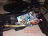
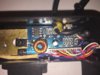
I wound up blowing a fuse on my gamecube which had a Zenith screen attached. I fixed the Gamecube, but do not know how to fix the screen bracket. The short was caused by using a 12v 3 amp portable battery with a homemade cable.
The bracket board seems simple, but I can't see anything labelled as a fuse. And I'm new to soldering and PCBs in general. Nothing immediately looks blown. Any ideas on where to look or how to troubleshoot this thing?
Thanks!
Edit: my homemade cable was just trying to replicate an Intec cable I have (barrel plug to GC connector). So either I blew it using voltage or incorrect polarity?
Also, the bracket power light is bright but dims when the screen is attached. It doesn't seem like the screen gets the power it needs.
Attachments
Last edited: