
You are using an out of date browser. It may not display this or other websites correctly.
You should upgrade or use an alternative browser.
You should upgrade or use an alternative browser.
Creating custom ROMs for the PS2
- Thread starter Epaminondas
- Start date
- Joined
- Dec 2, 2022
- Messages
- 18
- Likes
- 42
yes, .ELF files can be called from within the ROM.
tna9rish
.
- Joined
- Jan 16, 2025
- Messages
- 3
- Likes
- 1
Hey I would say thanks for this awesome stuff . But I don't know how to flash the bios with the tool you said. Now how do I flash the bios on my ps2 ?? and which hardware do I need to do it ?? . and thanks in advanceIn-system ROM flashing tool is now up on Github, in romflash repository under ps2dbg organization.
- Joined
- Dec 2, 2022
- Messages
- 18
- Likes
- 42
Flash Tool would be software tools for building new ROM images. A new application for this is currently under development. However, to have this on the console, the original BIOS chip must be replaced with a new chip with a custom ROM. Examples of chips that work are: MX29LV320, MX29LV640. These are the ones I use, but I believe others can also be used. You have to check the datasheet.
The original PS2 ROM chip cannot be re-flashed.
The original PS2 ROM chip cannot be re-flashed.
tna9rish
.
- Joined
- Jan 16, 2025
- Messages
- 3
- Likes
- 1
Thank you so much for the info . I know the ps2 rom in read only .But anyway really thanks for the efforts .Flash Tool would be software tools for building new ROM images. A new application for this is currently under development. However, to have this on the console, the original BIOS chip must be replaced with a new chip with a custom ROM. Examples of chips that work are: MX29LV320, MX29LV640. These are the ones I use, but I believe others can also be used. You have to check the datasheet.
The original PS2 ROM chip cannot be re-flashed.
tna9rish
.
- Joined
- Jan 16, 2025
- Messages
- 3
- Likes
- 1
Anyway I tried the bios of a 9K model on the pcsx2 emulator and it worked only that opl keeps loading . Also I tried the file that inside the folder where there is many files coz the file that generated output inside the custom just crashes the emulator .
Armorant
.
- Joined
- May 14, 2023
- Messages
- 4
- Likes
- 2
Edited: 11 of feb 2026
DO NOT USE THAT DESIGN!
IT WORKS on 70k - yes, but that one is complex and do need another extra PCB to work.
....
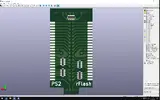
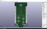
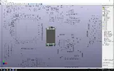
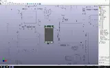
Designed to be installed on unpopulated TSOP-2-44 footprints (separate BOOT and DVD flashes). Mostly for GH-032/035, maybe 037. I hope that by using a 1.90 NTSC-U bios I would restore FHDB for 70k (confirmed) and get pros for MechaPWN'ed PAL consoles (not confirmed).
To install you need to remove TSOP-2-50 combined BOOTROM, tin the TSOP-2-44 pads both on PS2 and adapter side, align and solder as any BGA component by hot air station. It's better to use a small piece of capton tape to cover pads at PS2 side in the middle of TSOP-2-44.
PCB stack-up:4 layer, choose 0.6-0.8mm thickness at JLCPCB. Spacing between PS2 MOBO and top RF shield is 2.0mm, so we have 0.2+0.8+1.0mm limit (resistor arrays/PCB/flash). Better to choose 0.6mm (to do that select LeadFreeHASL or ENIG option)
To enable write operations connect circle pad to SWR signal (could be found at 70k SM)
MX29LV320/640 were kept in mind during making.
BOM list:
-x2 0402 100nF caps
-x5 Resistor Arrays concave 0402x4 560R
DO NOT USE THAT DESIGN!
IT WORKS on 70k - yes, but that one is complex and do need another extra PCB to work.
....
To install you need to remove TSOP-2-50 combined BOOTROM, tin the TSOP-2-44 pads both on PS2 and adapter side, align and solder as any BGA component by hot air station. It's better to use a small piece of capton tape to cover pads at PS2 side in the middle of TSOP-2-44.
PCB stack-up:4 layer, choose 0.6-0.8mm thickness at JLCPCB. Spacing between PS2 MOBO and top RF shield is 2.0mm, so we have 0.2+0.8+1.0mm limit (resistor arrays/PCB/flash). Better to choose 0.6mm (to do that select LeadFreeHASL or ENIG option)
To enable write operations connect circle pad to SWR signal (could be found at 70k SM)
MX29LV320/640 were kept in mind during making.
BOM list:
-x2 0402 100nF caps
-x5 Resistor Arrays concave 0402x4 560R
Attachments
Last edited:
R3Z3N
.
- Joined
- Oct 1, 2025
- Messages
- 5
- Likes
- 4
Wording is confusing. So you install it on unpopulated area where a ROM goes...but you have to remove and reinstall?
I assume you just mean desolder the BOOTROM and solder this on once MX29LV320/640 TSOP is flashed? Because on 70k that spot is already populated with the sony BOOTROM
I am curious...besides package, what is the difference between this and Tschicki's bootrom flex? This doesnt have AND gates I see...
I wouldnt mind ordereing some, already have 5 of Tschicki's flex to try. Looking also to add other drivers like mmce, hdd, etc for my crystal chip modchip fun. IE I already have the crystal chip booting BootManager (its interface/scripting interpreter) from hdd, mmce and usb but those drivers need to be on memcard, so having in rom would be nice.
Armorant
.
- Joined
- May 14, 2023
- Messages
- 4
- Likes
- 2
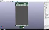
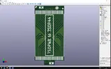
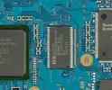
GH-032/035: TSOP-2-50 (combined BOOTROM) is installed and to the right of it you might see a half of TSOP-2-44 footprint. There is exactly the same at the bottom as well. My goal is to use 2 separate flashes, the Tschicki aims to replace that unified TSOP-2-50 BOOTROM which is harder, but also that is the only solutin for 79k-90k IIRCWording is confusing. So you install it on unpopulated area where a ROM goes...but you have to remove and reinstall?
I assume you just mean desolder the BOOTROM and solder this on once MX29LV320/640 TSOP is flashed? Because on 70k that spot is already populated with the sony BOOTROM
I am curious...besides package, what is the difference between this and Tschicki's bootrom flex? This doesnt have AND gates I see...
I wouldnt mind ordereing some, already have 5 of Tschicki's flex to try. Looking also to add other drivers like mmce, hdd, etc for my crystal chip modchip fun. IE I already have the crystal chip booting BootManager (its interface/scripting interpreter) from hdd, mmce and usb but those drivers need to be on memcard, so having in rom would be nice.
Attachments
Last edited:
- Joined
- Apr 28, 2026
- Messages
- 1
- Likes
- 0
Excuse me in advance if I ask anything stupid, I'm totally new to flashing custom ROMs.
I just got two 70k consoles (one GH-032, second is unopened yet) to resurrect their IDE port and this thread got me thinking on modifying the original ROM to add HDD drivers to boot directly from a drive.
Anyway, I think I will fabricate Armorant's PCBs, but I have a question:
How did you initially flash the memory chip? I don't have any expensive programmers, is it possible to use anything DIY here?
If I understand correctly with the SWR pin connected, later it can be reprogrammed using a software directly from the console, but I have to get there somehow.
Armorant
.
- Joined
- May 14, 2023
- Messages
- 4
- Likes
- 2
I will remove the gerber files from the message, you shouldn't use them, it's not a convenient option, it's difficult to install, although it works.Excuse me in advance if I ask anything stupid, I'm totally new to flashing custom ROMs.
I just got two 70k consoles (one GH-032, second is unopened yet) to resurrect their IDE port and this thread got me thinking on modifying the original ROM to add HDD drivers to boot directly from a drive.
Anyway, I think I will fabricate Armorant's PCBs, but I have a question:
How did you initially flash the memory chip? I don't have any expensive programmers, is it possible to use anything DIY here?
If I understand correctly with the SWR pin connected, later it can be reprogrammed using a software directly from the console, but I have to get there somehow.
Currently, there is no way to upload BOOT/DVD images directly by the PlayStation 2 iyself. You will need to use a programmer (for example, the XGECU T48 with the ADP_F48_EX_1 adapter).
You can PM me if you needed.
- Joined
- Jul 7, 2026
- Messages
- 1
- Likes
- 0
Hi, so i like have a 90001 board that i would want to experiment on but i dont know what rom chip i actually need, can someone fill me in on this info?
Similar threads
- Replies
- 11
- Views
- 8K
- Replies
- 32
- Views
- 8K