Honestly this one is a toughy. The 1.15v voltage traces and vias only exist in a very small part of the motherboard. I have circled that portion in red, the blue dots are 1.15v locations.
Top PCB face:
View attachment 40970
Bottom PCB face:
View attachment 40968
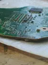
The short is
somewhere in that circle. If you can post some clear photos of that section of your trim, I can look for anything obvious, but you'll have a better chance eyeballing it under a magnifying glass from several angles.
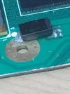
I recommend checking the via I have marked with a red arrow first. It's on the GND side of the big cap and the most likely to get accidentally blobbed.