Board scan Wii U Disc Drive Board Scans (VXX72135)

Lazr

.
Joined
Oct 3, 2023
Messages
105
Likes
292
Location
WA
Portables
Zero! Micro console gang 4 life!
Hey all! A few days ago I learned that the later Wii U ODD boards were 2 layers, so I sanded and scanned the VXX72135 (and from now on ill be referring to it as "35"). I did start to sand the VXX72132 (same thing, just "32"), but the 35 is almost identical to the 32 boards....and the 32 is 4 layers. The only difference is a possible main IC revision (it has the same amount of pins - although that doesn't mean its the same pinout) and the SDRAM on the back is rotated (horizontal instead of vertical).

There is a VXX72137 (37) revision board, which will need to be sanded and scanned separately, as it has no SDRAM (built into the main IC?), main IC is much smaller, and the whole board is a completely different shape (but it's still 2 layers!). I'll probably get around to this someday. I have many of these boards (all WUP-50s and probably all WUP-40s came with it).

GDrive link:

BitBuilt mirror

Crappy screenies:
1730006624755.png
1730006640090.png

1730006673596.png
1730006691295.png


Hope this helps someone with repairs or RE of the disc drive. :)
 
Last edited by a moderator:
So I'm gonna use this thread to info dump what I've learned about the disc drive, since:
A. Currently it's all in a group chat that's intended for other stuff.
B. There's almost no information about the disc drive anywhere.
C. No idea where else to do it.

The only components that require 5v are the motor driver and the "IC4002". The motor driver does exactly what it sounds like, drive the motors on the disc drive (it probably also takes in 12v, but I haven't traced that rail out yet). Removing that IC has zero consequences and the disc drive is happy. The same cannot be said about IC4002. I have no idea what this IC is, but it seems to take in 5v and then spit out 1v2 (among other things). Yes, I did just say 1v2. The Main IC on the disc drive runs on two voltages: 3v3 and 1v2.
1730445340145.png

(Red = 3v3, Purple = 1v2)

Originally I just shorted 3v3 and 1v2. Unfortunately that just caused the Main IC to get super hot and the disc drive wasn't recognized. How could I supply power to that rail...? Well, I still had parts from building Fujiflex', and in that BOM was a 1v2 LDO. On the flex its intended to take in 1v8, but the LDO will happily take in 3v3. Perfect! After removing IC4002 and wiring up the LDO, the disc drive was recognized! I then removed the 5v 0ohm resistor (or the fuse, there aren't any markings for the passives, so I have literally no idea what it is), and it still worked! I had essentially entirely eliminated the 5v requirement for the disc drive by using a simple LDO. I even trimmed the disc drive board for fun, since nothing on that side of the board was needed.
1730445184468.png
1730445210818.png

(The disc drive on the bottom in the left picture is where I tried shorting the two rails. Obviously verification would fail, but the disc drive just didn't do anything and resulted in 160-1400)

I also found a nice spot to put the LDO:
1730446930712.png

Not sure how much power the 1v2 rail draws, but the LDO seems fine for now.

Next thing I tried to remove was the SDRAM. Obviously it didn't work, but the way it didn't work was..interesting. The disc drive was failing verification (error 160-1402). Normally when the drive isn't found the console shows 160-1400, So the main IC was still functional. Probably just means that the AES engine uses some of the SDRAM, but no one knows, the disc drive firmware has yet to be extracted (that's kinda the goal with these scans: find how Nintendo/Panasonic programs these in the factory and somehow use that to dump the firmware).

I then cut off the other side of the board and tried to rewire SATA, and the console doesn't recognize the disc drive. I know SATA is two differential pairs, so I twisted some magwire tight with my dremel and rewired to the traces (honestly i should have just used the CM9/CM10 pads). The disc drive worked just fine with 3v3 and that 1v2 LDO, and it's definitely not bypassing the capacitors. I did this on a WUP-30, which entirely removes those capacitors (and the WUP-50 brought them back? WUP-40 is missing them too). I also tried rewiring some pullups/pulldowns for the lights, and still nothing.. Not sure what the deal here is. I'm sure I'll figure it out eventually, but for now I need to find another 35 drive board to test on.
1730446074139.png


Also, I noticed that there is a 3rd voltage..I think?
1730446252620.png

Measuring this with my meter I get 1v6. The weird thing about this voltage is that there are zero components for it besides some capacitors and certain traces have pullup resistors to it. Maybe the Main IC has some internal regulator? I don't think it's very important though, just something random I found.

I've also traced out the RAM, but there's nothing special going on there really.
1730446573692.png
1730446627986.png


Everything is sitting on an .xcf on my hard drive. I'll upload it to the google drive once I'm finished with tracing it all.
 
Last edited:
I uploaded the .xcf to the GDrive. It's largely unfinished, but since I haven't worked on it for awhile now figured I'd just upload it. No real point in keeping it on my hard drive.

It has:
- SDRAM traced out
- All Voltages traced out
- SATA connector traced out
- Motor Driver IC mostly traced out
- EEPROM(?) traced out

Have fun!
 
I also have a Wii U in the WUP-50 version. I also want to trim the disk drive board, which is precisely the model you did not sand yet (VXX72137) , but just like you, I do not have much information about this board, I also do not intend to sand mine, since this is the only one I have. But still so I would like to trim her one day, as soon as more information about her comes along (or you provide it) .
 
I dont have any scans with the soldermask or components removed, but i do have scans of them still in place. i was going to get copper scans but i wasnt very careful with the hot air and the copper started to delayer, i think.
 
How many disk drive models are there? And which one has the VXX72137 board inside?
 
theres 3 (that I know of) for the wiiu. the 37 drive board is found in most(?) WUP-40s and all WUP-50s.
 
I was referring to which drive model starting with RD-DKL (not the console motherboard revision) has the 37 board inside. Do you know which one have the mentioned board?
 
question : can we combine the wii and wiiu drives, by swapping the lens and motors from the wiiu one into the wii drive? if it was possible, you could play dvd's, bluerays, wii, gamecube, and wiiu games all from one console. wich would be really cool.
 
Question: Can we combine the Wii and Wii Drives, by swapping the lens and motors from the Wii One into the Wii Drive? If it was possible, you could play DVD's, bluerays, Wii, gamecube, and Wii Games all from one console.
This is technically impossible, because the optical unit of the Wii has nothing to do with the logic board drive of the Wii U. Ahh, but if we switched the logic board to the one of the wii as well? It wouldn't work either, because the Wii drive communication is the DI (disc interface), but the Wii U uses SATA (with some modifications)
 
This is technically impossible, because the optical unit of the Wii has nothing to do with the logic board drive of the Wii U. Ahh, but if we switched the logic board to the one of the wii as well? It wouldn't work either, because the Wii drive communication is the DI (disc interface), but the Wii U uses SATA (with some modifications)
but shouldent it

"
Screenshot 2026-05-04 200817.webp
" this is a truly beautifull ms paint mockup.

but yeah if you exchanged the parts that move the drive and disk, and the parts that decode the disk,
and keep the wii shell and mech to load the gamecube disk?
 
But should it?

View attachment 42740 this is a truly beautiful but paint mockup.

But yeah if you exchanged the parts that move the drive and disk, and the parts that decode the disk,
And keep the Wii Shell and Mech to load the GameCube Disk?
Mechanically, the Wii U drive can "read" the gamecube disk, but there is some limitation or software lock that causes the disk not to run. Which makes all this paraphernalia of your mockup kind of useless.
 
I was referring to which drive model starting with RD-DKL (not the console motherboard revision) has the 37 board inside. Do you know which one has the mentioned board?
Has anyone been able to solve this doubt?
 
shure, but dont we have a good controll over the software side?
Mechanically, the Wii U drive can "read" the gamecube disk, but there is some limitation or software lock that causes the disk not to run. Which makes all this paraphernalia of your mockup kind of useless.
 
The "control" even exists, but it delimits the system on the motherboard. The disk drive has its own protections. Nothing the system can do if the disk drive simply rejects the reading of the GC disk. I believe that there is no interest from the community in hacking the drive, since the homebrew by SD card and USB are much more evolved.
 
The "control" even exists, but it delimits the system on the motherboard. The disk drive has its own protections. Nothing the system can do if the disk drive simply rejects the reading of the GC disk. I believe that there is no interest from the community in hacking the drive, since the homebrew by SD card and USB are much more evolved.
true, true, but it would be cool, no?
 
Soon a new board cooked and sanded. Keep waiting...
 

Attachments

  • 17795414440053104920848075592529.webp
    17795414440053104920848075592529.webp
    3.4 MB · Views: 2
So I'm gonna use this thread to info dump what I've learned about the disc drive, since:
A. Currently it's all in a group chat that's intended for other stuff.
B. There's almost no information about the disc drive anywhere.
C. No idea where else to do it.

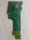
The only components that require 5v are the motor driver and the IC4002. The motor driver does exactly what it sounds like, drive the motors on the disc drive (it probably also takes in 12v, but I haven't traced that rail out yet). Removing that IC has zero consequences and the disc drive is happy. The same cannot be said about IC4002. I have no idea what this IC is, but it seems to take in 5v and then spit out 1v2 (among other things). Yes, I did just say 1v2. The Main IC on the disc drive runs on two voltages: 3v3 and 1v2.
View attachment 35930
(Red = 3v3, Purple = 1v2)

Originally I just shorted 3v3 and 1v2. Unfortunately that just caused the Main IC to get super hot and the disc drive wasn't recognized. How could I supply power to that rail...? Well, I still had parts from building Fujiflex', and in that BOM was a 1v2 LDO. On the flex its intended to take in 1v8, but the LDO will happily take in 3v3. Perfect! After removing IC4002 and wiring up the LDO, the disc drive was recognized! I then removed the 5v 0ohm resistor (or the fuse, there aren't any markings for the passives, so I have literally no idea what it is), and it still worked! I had essentially entirely eliminated the 5v requirement for the disc drive by using a simple LDO. I even trimmed the disc drive board for fun, since nothing on that side of the board was needed.
View attachment 35926View attachment 35928
(The disc drive on the bottom in the left picture is where I tried shorting the two rails. Obviously verification would fail, but the disc drive just didn't do anything and resulted in 160-1400)

I also found a nice spot to put the LDO:
View attachment 35935
Not sure how much power the 1v2 rail draws, but the LDO seems fine for now.

Next thing I tried to remove was the SDRAM. Obviously it didn't work, but the way it didn't work was..interesting. The disc drive was failing verification (error 160-1402). Normally when the drive isn't found the console shows 160-1400, So the main IC was still functional. Probably just means that the AES engine uses some of the SDRAM, but no one knows, the disc drive firmware has yet to be extracted (that's kind of the goal with these scans: find how Nintendo/Panasonic programs these in the factory and somehow use that to dump the firmware).

I then cut off the other side of the board and tried to rewire SATA, and the console doesn't recognize the disc drive. I know SATA is two differential pairs, so I twisted some magwire tight with my dremel and rewired to the traces (honestly I should have just used the CM9/CM10 pads). The disc drive worked just fine with 3v3 and that 1v2 LDO, and it's definitely not bypassing the capacitors. I did this on a WUP-30, which entirely removes those capacitors (and the WUP-50 brought them back? WUP-40 is missing them too). I also tried to rewiring some pullups/pulldowns for the lights, and still nothing. Not sure what the deal here is. I'm sure I'll figure it out eventually, but for now I need to find another 35 drive board to test on.
View attachment 35931

Also, I noticed that there is a 3rd voltage. I think?
View attachment 35932
Measuring this with my meter I get 1v6. The weird thing about this voltage is that there are zero components for it besides some capacitors and certain traces have pullup resistors to it. Maybe the Main IC has some internal regulator? I don't think it's very important though, just something random I found.

I've also traced out the RAM, but there's nothing special going on there really.
View attachment 35933View attachment 35934

Everything is sitting on an .xcf on my hard drive. I'll upload it to the google drive once I'm finished with tracing it all.
How can you put these colored markings on top of the PCB tracks?
 
How can you put these colored markings on top of the PCB tracks?
Any image manipulation software. I used GIMP but theres also paint.net and Inkscape people like to use.
 
I finally had time to sand and scan my VXX72137 board. I hope it will be useful for those who want to trimming and, who knows, put in LOLWUT board without sacrificing compatibility with vWii.

Feel free to add this content to the Yveltal compendium.

 
Back
Top