cy
.
- Joined
- Sep 3, 2020
- Messages
- 186
- Likes
- 543
- Portables
- 8
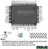
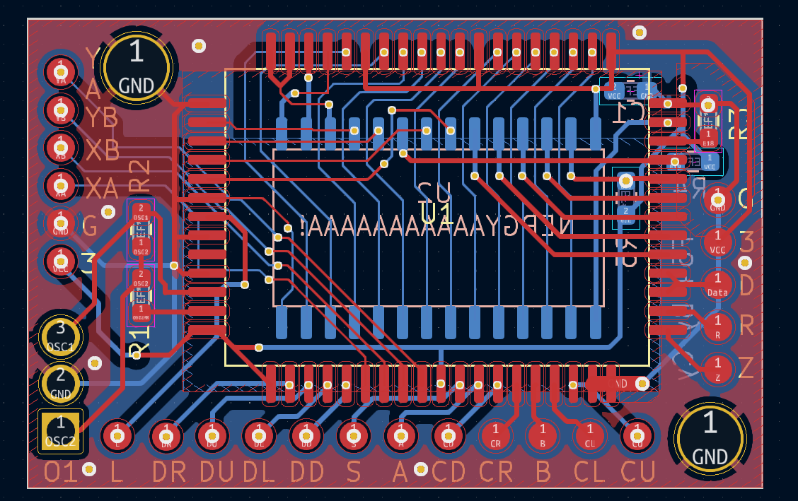
As many of you know, I've been working for quite a while now on an N64 portable of my own. Along the way I've developed several of my own PCBs including an N64 controller relocation PCB. This board allows you relocate the NUS-CNT controller chip and oscillator found on OEM N64 controllers. The F64 also features a footprint for FRAM chips like this allowing for built-in controller memory pak functionality! I've gotten several requests now for the files for (or files related to) this project and I've been meaning to release them so here they are!
I'd like to thank @Gman and @SparkleBear for sharing helpful diagrams, providing useful information, and providing component links such as the link for the FRAM chip provided by Gman. I'd also like to thank @CrazyGadget and @Y2K for helping me learn the basics of KiCAD so I could streamline something with so many connections.
Resistor values:
R1 = 5.6k
R2 = 1M
R3 = 10k
R4 = 10k
R5 = 10k
Capacitor value:
C1 = 1Uf
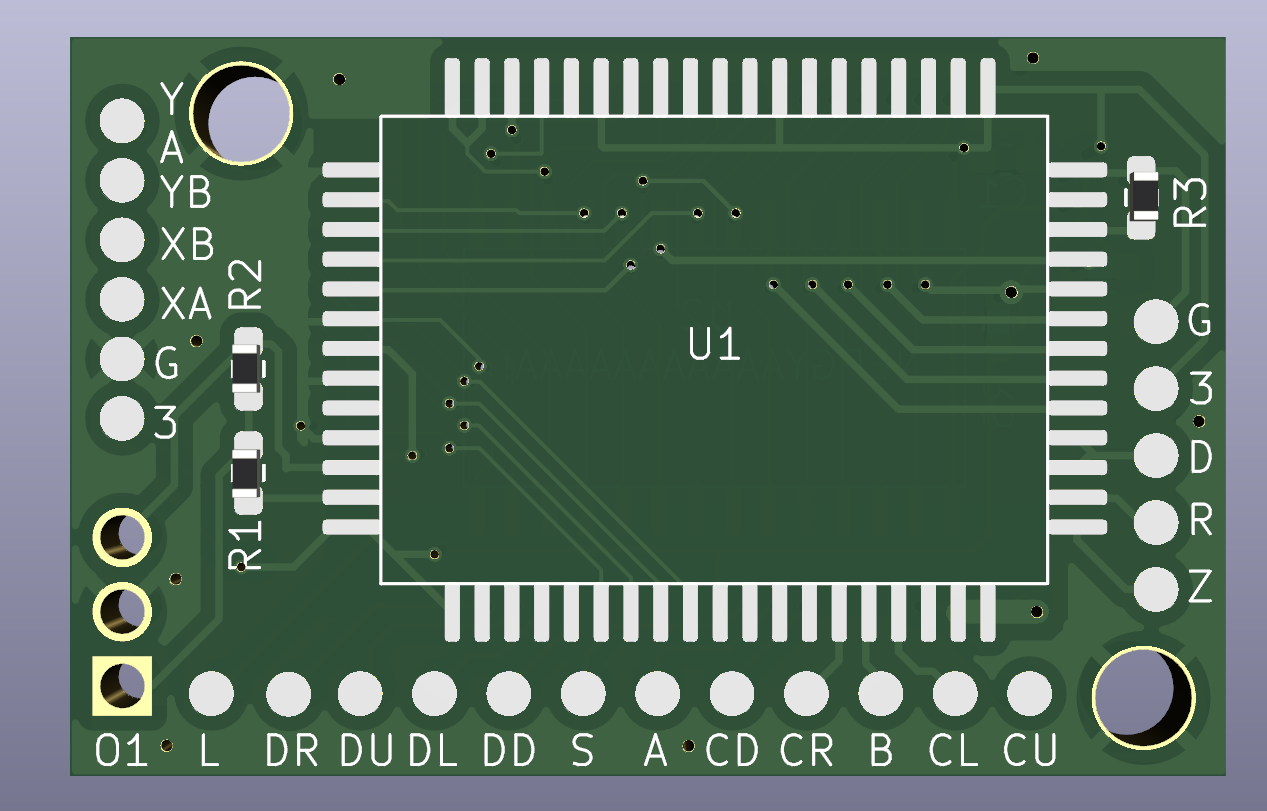
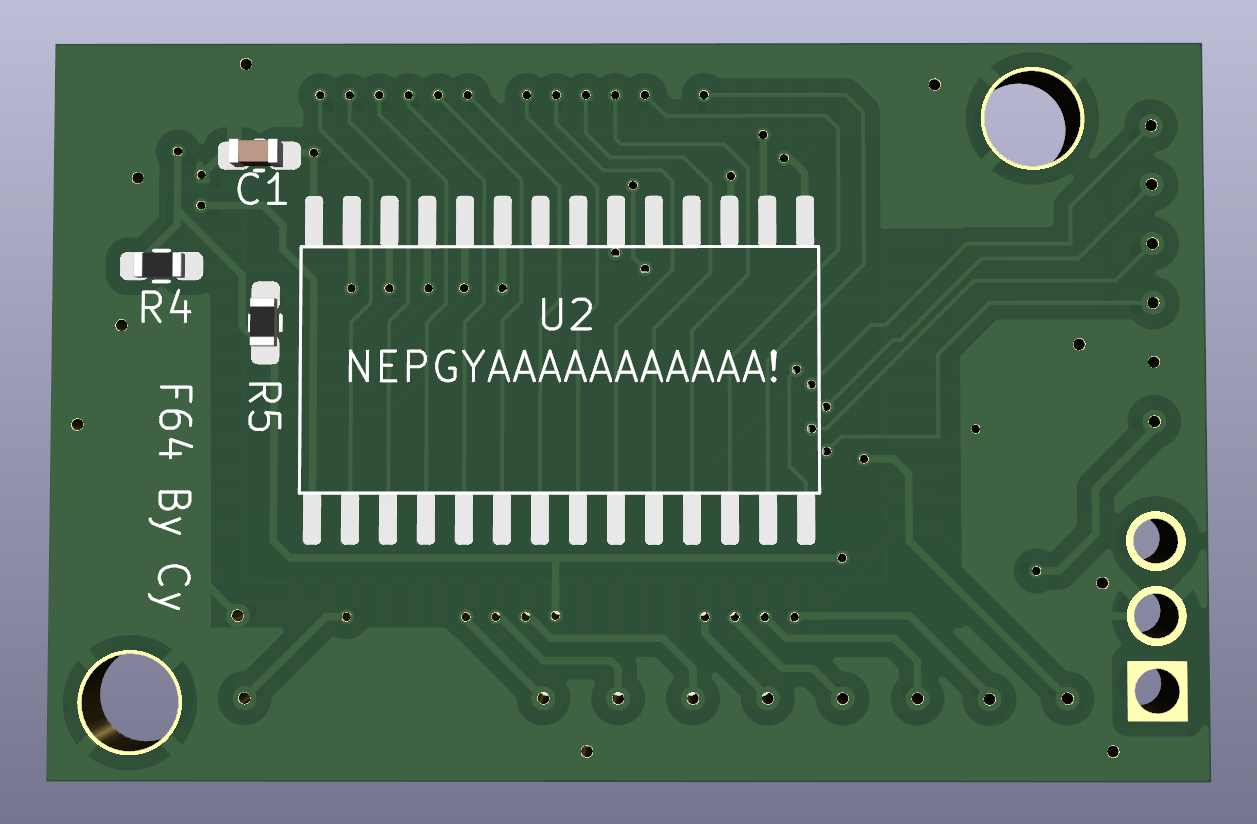
FRAM Chip orientation:
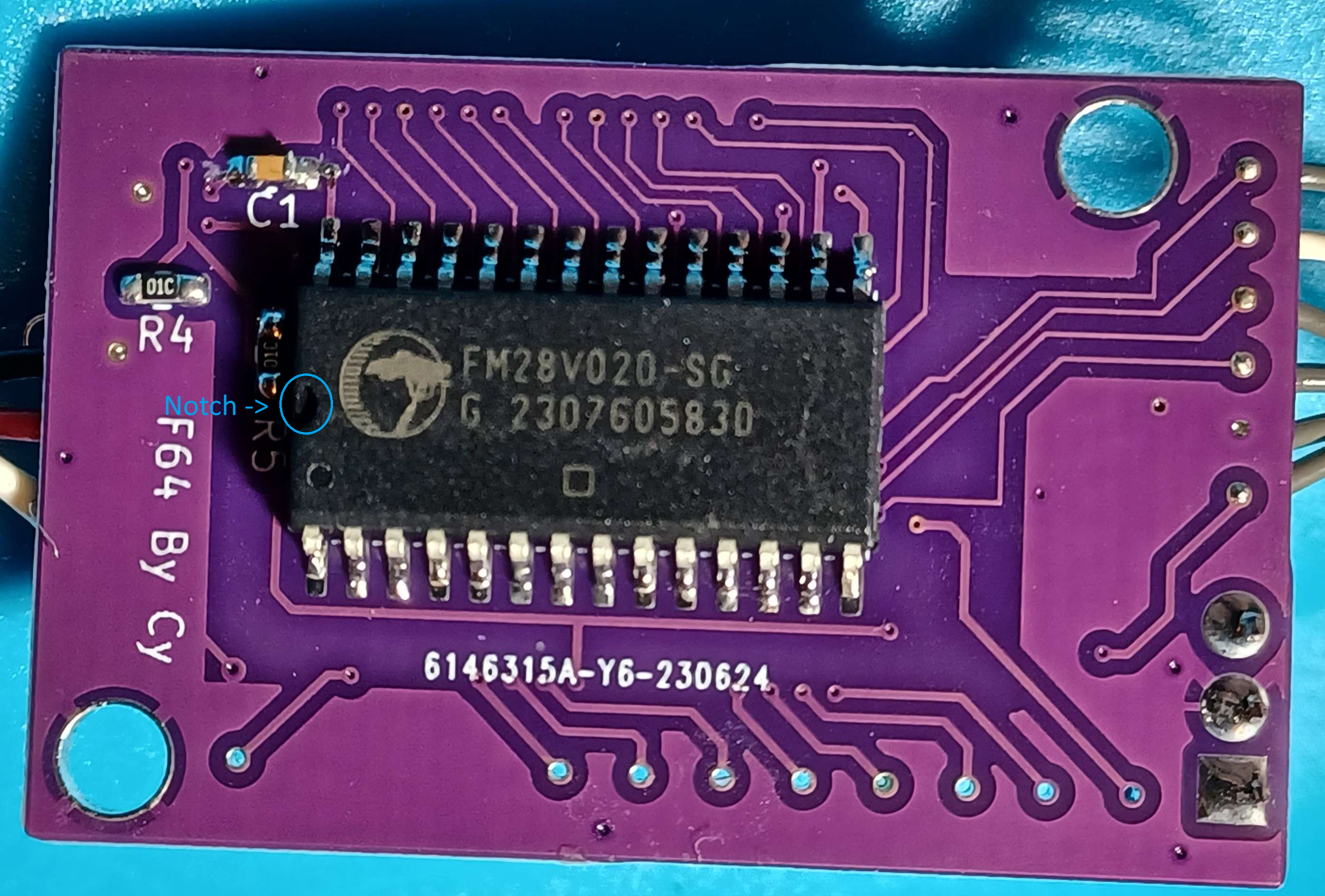
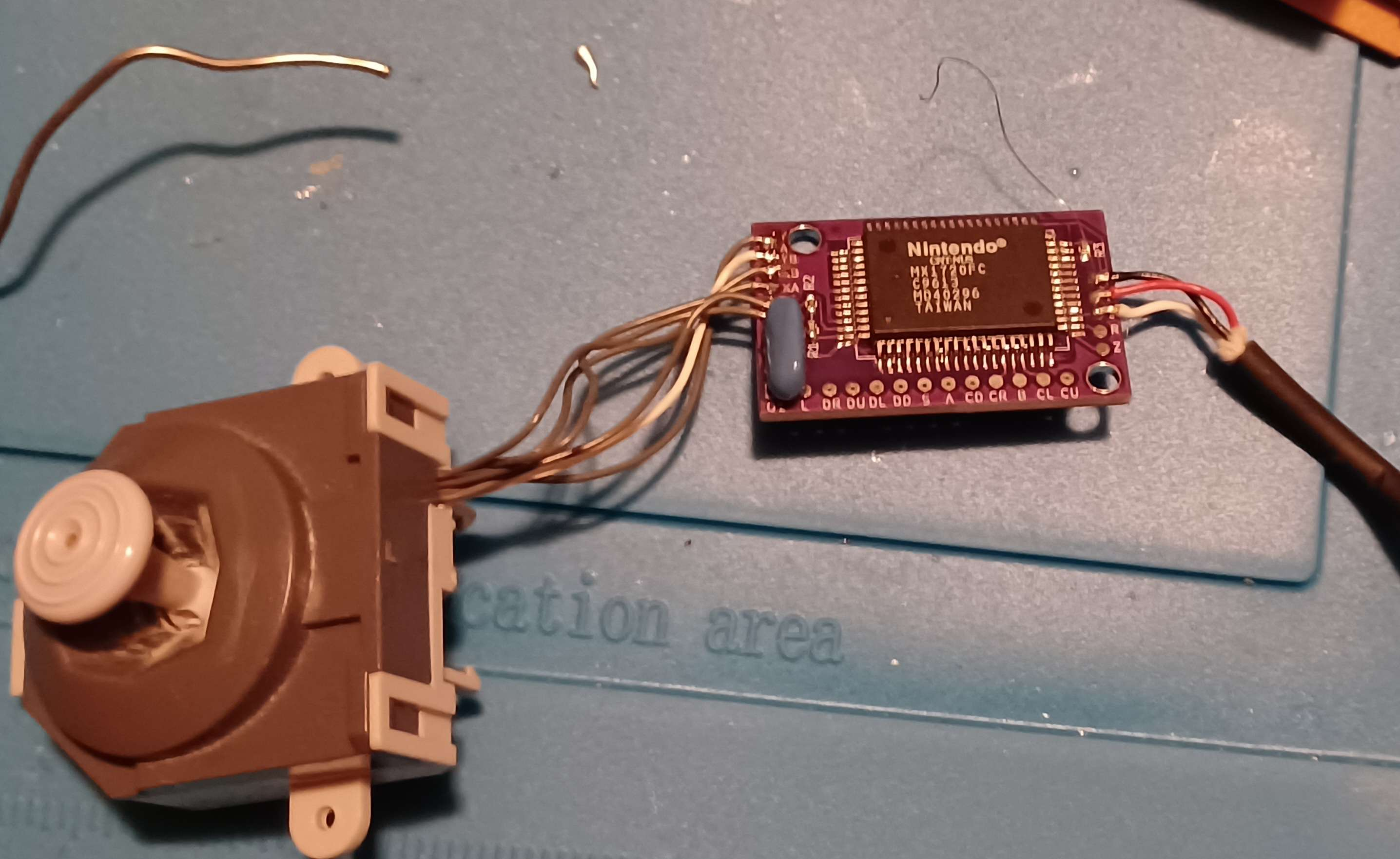
Here are some shots of the CAD work as well as a pic of it fully assembled:
I have included the KiCAD files as well as the files one would need to upload to JLCPCB to order a batch of these.
Enjoy! And if anyone has any questions feel free to leave them in a post below!
I'd like to thank @Gman and @SparkleBear for sharing helpful diagrams, providing useful information, and providing component links such as the link for the FRAM chip provided by Gman. I'd also like to thank @CrazyGadget and @Y2K for helping me learn the basics of KiCAD so I could streamline something with so many connections.
Resistor values:
R1 = 5.6k
R2 = 1M
R3 = 10k
R4 = 10k
R5 = 10k
Capacitor value:
C1 = 1Uf
FRAM Chip orientation:
Here are some shots of the CAD work as well as a pic of it fully assembled:
I have included the KiCAD files as well as the files one would need to upload to JLCPCB to order a batch of these.
Enjoy! And if anyone has any questions feel free to leave them in a post below!
Attachments
-
110.3 KB Views: 33
-
66.2 KB Views: 35
-
67.8 KB Views: 29
Last edited: