Worklog Desktop Arcade Wii Worklog

Joined
Nov 6, 2023
Messages
9
Likes
13
Location
Upper Left, USA
Hey all, first project. I got into the idea of portablizing as a kid when I picked up Ben Heck's book and tried to build a portable NES. I did not get very far, but now that I'm older with disposable income and a slightly better attention span, I wanted to give this a proper attempt. I'm starting with a step below full-on portabilizing since my experience soldering so far has mostly been messing around on old electronics from goodwill.

The idea is to make a desktop arcade "cabinet" - a Wii with a modified Miicro trim (as I have a 4 layer board) wired up to a screen and speakers built into a custom case. I don't plan on doing any relocations to simplify this first project, and focus on this mostly as a GameCube machine and an emulator. Also accepting name suggestions, "Desktop Arcade Wii" is a bit wordy.

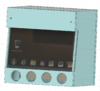
As for the case itself, I have mocked up a concept as a first attempt as I'm also learning Fusion 360. I may just end up frankencasing this into a box to start. I really liked the idea of adding a sensor bar into the cabinet and being able to play Wii games, but trying to prevent scope creep. See the attached photo.

Progress:
- Acquired two Wiis from goodwill, expecting that I would need a backup
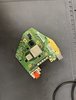
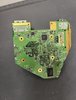
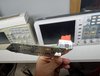
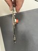
- First attempt at relocating U10 was ruined by a short, and then I broke a pin trying to detach it to fix the short. I then broke a pin trying to relocate U9. Turns out the backup Wii was needed immediately lol. But was able to use U10 and successfully complete the relocation, and I learned a valuable lesson about how to be gentle with components on the board :).
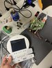
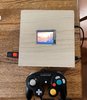
- Relocated Wii boots - I know is a small step for some but it makes this project feel legitimate and possible to me now.
- Next up - the trim.

I'll posts some pics of the trim hopefully tomorrow. I realize doing a custom trim is ambitious for a first project, but I figured since the Miicro (and the adapted version I planned for the 4 layer) is well outuside the OMGWTF trim, if I am not successful I can retry with a proper OMGWTF trim. Once I know I can actually get the trim working, I'll feel a lot more confident about concrete plans for the rest of the project (screen, dimensions, etc).
 

Attachments

Stitches

2 and a Half Dollarydoos
Staff member
.
.
Joined
Feb 5, 2017
Messages
3,848
Likes
3,025
Location
Banana Bender Land, Australia
Portables
6
I like this idea. Always nice to see more multiplayer centric builds
 
Joined
Nov 6, 2023
Messages
9
Likes
13
Location
Upper Left, USA
Did my first trim today. Tested resistances and it looks like I have a short on the 3.3v line. Tried removing components on the edges and retesting but no dice. Assume that it's a problem with the trim - either I need to sand more, or the trim itself is bad and I'm shorting something that way.

I did cover the CPU and GPU with kapton tape, but forgot to do so for the NAND. Thinking cleaning up everything with isopropyl is probably not a bad idea post trim and desoldering anyways, and after that see if more sanding solves this problem. If neither of those help I'm going to try and cut this to an OMGWTF trim.

Otherwise, any feedback would be appreciated.
 

Attachments

Joined
Jan 27, 2023
Messages
80
Likes
40
Location
MX
Portables
2
Hi drum! I hope this tip can help you

-I'm not sure how did you finish the board's edges while sanding, but try to reach this shape to ensure that layers doesn't touch each other (the layers are the yellow ones):
1707495516988.png


My first two boards where shorted until I reached this shape on the edges
 
Joined
Oct 22, 2021
Messages
38
Likes
17
Location
Canada
You know, I’ve never trimmed a 6 layer board, but for the 4 layer board I trimmed I would sand the edges at a small angle. This puts just a little bit more space between the edges for preventing shorts. Just make sure you don’t accidentally sand down one of those large capacitors like I almost did.
 
Joined
Nov 6, 2023
Messages
9
Likes
13
Location
Upper Left, USA
Thanks for the suggestions all! As it turns out, some scrubbing with IPA and a toothbrush fixed everything right up. And in exciting news, it boots! I wasn't able to get USB working (the picture is missing the 5v wiring), but the fact that everything else works fine leads me to believe I'm just missing a step.

Once I fix up the USB, I'll wire up the controller ports next. I also plan on probably redoing this wiring as it's a bit shoddy. I'll also need to start finalizing my case plans, now that I know this works trimmed.
 

Attachments

Joined
Jan 27, 2023
Messages
80
Likes
40
Location
MX
Portables
2
Were you able to get USB working?

I saw that twisting the USB data+ and data- cables helps a lot (considering that you have the right polarity)

Also check if you’re receiving more or less than 5v on USB port
 
Joined
Nov 6, 2023
Messages
9
Likes
13
Location
Upper Left, USA
Yup - so I didn't relocate USB, since the intention was to do a Wii Micro-style "portable". The issue was twofold - first, I didn't power the USB with 5v, and second, I didn't actually enable the 5v regulator on my RVL-PSU. After doing both, I was able to get it to work.

I wired up the controller, attached it to a tiny screen I had handy, and attached heatsinks, and now I have a playable Wii Micro! I put it into a wooden project box to give myself something playable while I wait for the remaining parts (bigger screen, RVL-AMP) to come in.

It looks so goofy with the tiny screen but I love it. I want to find some sort of project using this tiny screen.
 

Attachments

Joined
Jan 27, 2023
Messages
80
Likes
40
Location
MX
Portables
2
Great

Looks amazing as it is!
In my first portable I had a 4” screen and looked really good even without trimming the wii
 

Stitches

2 and a Half Dollarydoos
Staff member
.
.
Joined
Feb 5, 2017
Messages
3,848
Likes
3,025
Location
Banana Bender Land, Australia
Portables
6
Yup - so I didn't relocate USB, since the intention was to do a Wii Micro-style "portable". The issue was twofold - first, I didn't power the USB with 5v, and second, I didn't actually enable the 5v regulator on my RVL-PSU. After doing both, I was able to get it to work.

I wired up the controller, attached it to a tiny screen I had handy, and attached heatsinks, and now I have a playable Wii Micro! I put it into a wooden project box to give myself something playable while I wait for the remaining parts (bigger screen, RVL-AMP) to come in.

It looks so goofy with the tiny screen but I love it. I want to find some sort of project using this tiny screen.
Grats on the working trim! You're doing well
 
Joined
Nov 6, 2023
Messages
9
Likes
13
Location
Upper Left, USA
Update, this board is dead. I managed to sever the connection between the P1 controller rewiring via and the RA1. Not exactly sure how it happened, but the magnet wire I was using was way too thick, so I re-did the connections over and over again - ended up using way too much heat, being sloppy with the iron, etc. I tried a few ways to work around it and eventually burnt off the pads under RA1, which at that point I realized I wasn't going to be able to salvage this.

Disappointing, but it doesn't feel like such a huge setback. I learned some good lessons (and also going to switch over to leaded versus lead free solder, another reason I was using too much heat). And I can harvest the broken board for parts - I'm going to make keychains out of the CPU/GPU.

Luckily I have another board handy. I'm going to try a full OMGWTF trim now, since I feel way more confident about both my trimming and wiring abilities.
 
Joined
Jan 27, 2023
Messages
80
Likes
40
Location
MX
Portables
2
Do you mean that you have severed the whole blue trace for P1?

Traces.png
 
Joined
Nov 6, 2023
Messages
9
Likes
13
Location
Upper Left, USA
I severed the trace where the red X is. The via circled in green was also heavily scratched up, and I might have burnt the via in itself - trying to test the connection between that via and the via above showed no continuity.

From my understanding of searching the forum, RA1 serves as a resistor array as a 750(?) ohm resistor connecting the controller vias to 3.3v. So I tried to work around the above with these methods:
- I tried to wire output from another pin on RA1 to the P1 via, in an effort to connect power to it, but that didn't work.
- I tried to connect 3.3v and a 750 ohm resistor to P1 via, but that also didn't work.
- For the above two, I tried the circled green via as well as the P1 via above.

The controller ports themselves measured with the correct voltage and showed continuity when I tested them.

I think my problem was using _way_ too much heat, both in factor of using lead-free solder and setting the iron temperature hotter, as well as redoing the joint enough touching the iron to the board for far too long.

Edit: I can post a picture of the board for posterity, at least as a lesson in what not to do.
 

Attachments

CrazyGadget

Crazy Helpful, CrazyGadget
.
Joined
Jun 6, 2020
Messages
611
Likes
879
Location
Downing's Closet
Portables
???
If the via itself is still in tact, that can absolutely be salvaged. Even if the P1 via you circled is toast, you can still use the other P1 via in that image (that's the one that actually goes to the GPU). As for the severed trace to the pullup resistor, you can add a separate pullup on the port-end of the line (I know you mentioned already trying that but it's worth another shot). Doing it on the port side will give you more meat to solder the resistor to.

As for your issues leading to this, there are a lot of factors that go into a good soldering experience:
  • The soldering iron itself
    • You really want to be using something temperature-controlled. Based on what you have said, I'm going to assume you have one, hopefully with an accurate temperature set. You also want to make sure your iron has good thermal stability (the ability to stay at-temperature, even when soldering to large planes). Lack of good thermal stability will lead to poor thermal transfer (how quickly you can transfer heat from your iron to the board), leading to having to spend more time on a joint, leading to burning things...
  • The tip you are using
    • Just like above, what tip you use has a major role in the overall thermal transfer of your iron. If you are running something like a pencil tip, there is very little area for the tip to make contact with the joint. If you use something like a chisel tip, there is a much larger surface area of the tip making contact with the joint --> better thermal transfer!
  • The temperature you are running
    • Contrary to popular belief, a hotter iron is not a bad thing! I like to keep my iron between 700-750F. The key to good soldering is not keeping the temperature low, but rather keeping the time spend on the joint low. If you keep your iron at too low of a temp, it will take longer for the joint to heat up, and the surrounding board will wick up what heat you are giving the joint. More time spent trying to get the joint to heat up = problems! If you run your iron hotter, you are better able to quickly get a joint up to temp without the surrounding board wicking away the heat --> lower time spent on the joint!
  • The solder you are using
    • As you have mentioned, lead-free solder sucks. Leaded solder behaves so much better. That being said, not all leaded solder is made the same! Ask almost here, and we will recommend Kester 63/37. Once you use it, you will never go back!
  • The flux you are using
    • Just as important as having good solder is having good flux to facilitate good joints! There's more a debate on what is the "best," but some fan favorites here are Amtech NC-559-V2-TF, MG Chemicals 8341, and Chipquik SMD291.
Send some pictures of your board, I bet we can get it going!
 
Joined
Nov 6, 2023
Messages
9
Likes
13
Location
Upper Left, USA
Thanks for all the suggestions and help! That's good to know about the soldering iron heat - makes sense my problem was way more that I was holding the tip on the vias for way too long, since I was trying to get all four controller ports connected. I did also use way too broad of a tip at first - I did switch to a finer one, but I don't know if the damage was done at that point.

It's probably worth mentioning that I already ripped off the CPU from this board - I want to make a keychain or CPU collage of some sort for my office wall. Even then some people here might still be able to repair a detached CPU, but I'll throw in the towel there :). Still, I'll be sure to double check here before calling it on a board in the future, hate to waste something salvageable.

I'm hoping I'll get time to trim the other board this weekend, so ideally this project will be right back on track. My new plan is to do this project in two phases - first phase will have the system in a simple rectangle case running on battery power, with composite display and all four controller ports connected. This will be enough of a test in ironing out the kinks of 3D printing a case with correct port openings and measurements.

Once that's done, I want to move it to a case designed like a smaller arcade cabinet (a-la the original image for this project). Here, I'll switch to VGA and adding audio with speakers in the "cabinet".

One question - what AWG magnet wire do people usually use for data wires like controller ports, VGA, audio, etc? I initially was using 26 AWG since it's the magnet wire I had handy, but realized that was probably too thick, so I moved to 32 AWG - at that point the damage to this board may have been done though.
 
Joined
Jan 27, 2023
Messages
80
Likes
40
Location
MX
Portables
2
- I tried to wire output from another pin on RA1 to the P1 via, in an effort to connect power to it, but that didn't work.
- I tried to connect 3.3v and a 750 ohm resistor to P1 via, but that also didn't work.
- For the above two, I tried the circled green via as well as the P1 via above.
Sorry bro, I was about to suggest placing a resistor between 2 vias
IMG_4047.jpeg

Hope doing another try fix the problem
 
Joined
Oct 27, 2020
Messages
108
Likes
120
Portables
KiWii Portable (In progress)
Oh this is sick! I was actually going to plan something super similar to this, basically a very scaled down replica of an old arcade cabinet, with a trimmed wii and external controller ports, can't wait to see the result!
 
Top