
Hey all,
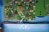
I've noticed a change on the RVL PMS I have vs what's used in the manual and need some guidance. In section 7, Wiring the USB, step 3 shows the location of the VSYS as being in center lower left of the board, whereas my board has a pad on the lower left corner. Images attached showing these locations. Later in section 12, step 3, the manual says to run a wire from "one of the capacitors on the VSYS plane" to the power pad on the RGB board. My question is with where my VSYS connection is, which capacitor should I connect the RGBs power to?
I've noticed a change on the RVL PMS I have vs what's used in the manual and need some guidance. In section 7, Wiring the USB, step 3 shows the location of the VSYS as being in center lower left of the board, whereas my board has a pad on the lower left corner. Images attached showing these locations. Later in section 12, step 3, the manual says to run a wire from "one of the capacitors on the VSYS plane" to the power pad on the RGB board. My question is with where my VSYS connection is, which capacitor should I connect the RGBs power to?
Attachments
-
 779.3 KB Views: 204
 -
 673.2 KB Views: 252
 .
.