Worklog N64 Portable V3

Joined
Jan 18, 2019
Messages
34
Likes
66
Afternoon folks!

I've been lurking around this forum for years, having originally started over on ModRetro... That'll probably give a sense of how long this has been a hobby of mine :ding!:

I've been planning in my head for years to tackle a third revision of my early attempts of building portable N64's, and even at times picked up my soldering iron and done a few trims... but life consistently gets in the way... everything gets packed into a box and forgotten about. :(

I'm hoping this time round to see the project through! I have access to far more resources, have far more skills and innovations from others has moved on greatly from when I first ventured into portables!

I'll detail more at a later date when things start moving along, but right now, I just want to get a good trim sorted and buy up all the bits I need to make my vision a reality! So a few questions if anyone can guide me!


- I've never used Magnet wire on my previous builds, but I will definitely need to use it on this build. I'm considering a RCP cartridge slot, so need to know what gauge is most reliable?

- I bought one of GMAN's U-Amp's quite a few years ago... I'm not overly fussed about replacing it with a N64Amp if I can help it. Can I just use the Analogue inputs? If so, what impedance speakers can I use with the U-Amp? I was just thinking DS speakers again?

- Switch joysticks. Can anyone point me towards guides/ code to use them with the N64 controller? I have seen GMAN has some code on Github, will this work/ need tweaking to work? I am going to be learning to program IC's for this project; I've never done it before, but have managed to convince my workplace to pay for some training and MPlabs debugger, haha.


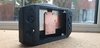
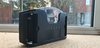
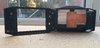
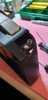
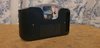
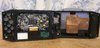
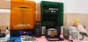
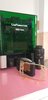
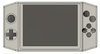
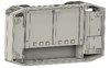
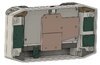
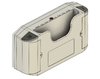
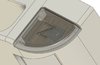
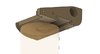
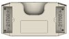
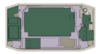
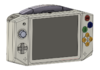
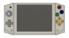
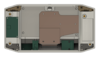
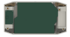
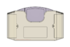
And because everyone love photos, here was one of the last images I had of my V2 before life got in the way. Behold DIY vacuum formed, hot glue glory from a decade ago!


Thanks for the help in advance everyone! :)
 

Attachments

Joined
Oct 5, 2019
Messages
132
Likes
122
Portables
2
- I've never used Magnet wire on my previous builds, but I will definitely need to use it on this build. I'm considering a RCP cartridge slot, so need to know what gauge is most reliable?

Here is a post saying that 30 gauge should be okay for the RCP. https://bitbuilt.net/forums/index.php?threads/rcp-27-28wiring-guide.1516/post-19579


- I bought one of GMAN's U-Amp's quite a few years ago... I'm not overly fussed about replacing it with a N64Amp if I can help it. Can I just use the Analogue inputs? If so, what impedance speakers can I use with the U-Amp? I was just thinking DS speakers again?

I am using these speakers (https://www.digikey.com/en/products/detail/soberton-inc/SP-1511S-1/6099099). The impedance is 8 ohms. I'm sure others will work but these are ones I know work.


- Switch joysticks. Can anyone point me towards guides/ code to use them with the N64 controller? I have seen GMAN has some code on Github, will this work/ need tweaking to work? I am going to be learning to program IC's for this project; I've never done it before, but have managed to convince my workplace to pay for some training and MPlabs debugger, haha.

There aren't really any full guides on the controller piece of an N64 build. A few people have made their own PCBs that work with GMans code but they are closed source. I just went through the effort of learning how to program IC's on my project as well. If you have any questions feel free to reach out. It took me a while to figure out how to flash things properly.
 
Joined
Jan 18, 2019
Messages
34
Likes
66
Evening folks,

Progress has been both slow and yet I've achieved more in the past week than I have in the past decade trying to get this off the ground again!


As a typical engineer I am TERRIBLE at documenting things, but with my hyper focus currently in overdrive at the moment, I've thrown some screen shots together of the CAD work; easily 30 hours+ of design work has gone into this and it is by no means finished.

Still needs:
- Relocate my breakout board.
- Add start button.
- Add bespoke PCB footprints and position.
- Add screen control board.
- Add all face buttons and their respective support channels.
- Add audio amp mounting and speaker positions (I can't decide on a final speaker grille design...)


The high level spec list:
- 2x 21700 @4800mAh a piece.
- 4:3 screen 5" screen.
- Switch joystick.
- Custom PCB to house FRAM, face button contacts, CNT-NUS, Logic Gates for volume/ screen controls, PIC for Switch joystick.
- Bespoke CNC copper heatsink.
- Laser cut aluminium plate to further dissipate copper heatsink and support heatsinks for chipsets. Also a 'heat channel' behind the plate to vent.
- Gman power and audio.
- Breakout boards for power and data between upper and lower case halves.
- Polycarbonate screen cover bonded to upper case.
- And lots more!

Bits I will need help with:
- The joystick PIC controller - this is completely new ground for me; work are giving me some training and support, but could definitely do with some hand holding on here!

Without further ado! Pictures of the CAD work, any criticism and design thoughts welcome :)
 

Attachments

Joined
Jan 18, 2019
Messages
34
Likes
66
So some updates!

I've spent a ridiculous amount of time continuing with the CAD model. I did a preliminary print after my last post which highlighted a lot of snags (and ugly print issues despite being printed on a stupidly expensive professional printer).

Custom heatsink has been made, albeit the friend I got to do it buggered the hole sizes up, so they'll be M5 vs the M4 I had spec'd. They also did not get the reverse face perfectly paralell... so now I will need to machine it myself parallel... reducing the overall thickness from 3mm to 2.7mm... But should be a quick job, I've already laser cut some custom parallels to sit it in the mill.

Issues identified and rectified:
- Cartridge slot too slack

- Trigger buttons did not have a 'positive' feel - increased the travel length and added a small spring to increase resistance. Works much nicer now.

- Face buttons were a bit tight and I have had to accept, using the original buttons will look stupid considering the level of design work that has gone into this. So I will SLA some new buttons. Which I can then try and resin cast them in their final colour.

- Screen opening was a tad too large.

- Reduced the overall thickness by 2.5mm to a final thickness of 48.3mm.

- The lower corners uncomfortably pressed into your hands when being held - these have now been smoothed off to hopefully make the whole thing more ergonomic.

- Button positions altered to be more accessible in a handheld format. Keeping the A+B buttons in their old position did not naturally fall into a natural range of reach.

- Every internal fixing has been replaced with heat set brass inserts - M1.6, M2, M2.5 and M4. (apart from the cartridge slot support which will have a hexagon printed for a standard M3 nut)

- Custom PCB footprints have been designed ready to run through KiCad or some of the more powerful packages I have access to.

- Screen PCB standard capacitors are a too chonky and will cause the whole case to increase 4 - 5mm in thickness; so I've got some Tantulum capacitors to reduce this.

- Power LED hole added to front and lots, lots more work has been done.


I'll hopefully get the next print sorted this week, if it comes out good enough, I'll try and finish/ paint it. If not, I'm owed some favours to have it printed in SLA or potentially SLS... Although, I have some confidence the ABS prints with fettling/ vapour polishing/ sanding/ shouting/ filling, will produce a professional finish... again, I do a lot of manufacturing favours for other people, so I'm owed favours in the painting department also :XD: 
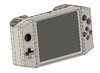
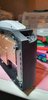
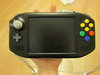
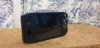
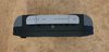
Just need to decide upon a final colour, anyone have any thoughts? I'm potentially leaning towards keeping it simple and black?
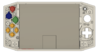

Anyway, without further ado, (at least) another 40 - 50 hours of CAD tinkering later, something that no doubt looks remarkably similar to the last images you saw! :XD::XD: But I can assure you, optimising the design is what takes the real time.


Thoughts, questions, feedback all very welcomed! :)
 

Attachments

Joined
Jan 18, 2019
Messages
34
Likes
66
I've rigged my screen up at 5v and it appears to work without removing one of the buck converters; what are peoples thoughts? Should I still remove the converter as per the guides on here or just wire it straight in with 5v? :rothink:
 

Attachments

Joined
Oct 5, 2019
Messages
132
Likes
122
Portables
2
I've rigged my screen up at 5v and it appears to work without removing one of the buck converters; what are peoples thoughts? Should I still remove the converter as per the guides on here or just wire it straight in with 5v? :rothink:
Thats surprising, but I've never tried powering the screen before modifying it. If it works then I don't think it should be a problem.
 

Stitches

2 and a Half Dollarydoos
Staff member
.
.
Joined
Feb 5, 2017
Messages
3,848
Likes
3,025
Location
Banana Bender Land, Australia
Portables
6
I've rigged my screen up at 5v and it appears to work without removing one of the buck converters; what are peoples thoughts? Should I still remove the converter as per the guides on here or just wire it straight in with 5v? :rothink:
Up to you. Leaving the 5v reg on may cause some instability, and you'll have ever so slightly higher power draw from thermal inefficiency. But, if it's working as is then you can just leave it for simplicity. Also, some driver boards step the input voltage down to 3.3v rather than 5v, and I can't remember which voltage those KYV-N2 V6 boards use. I'd check the onboard reg's output voltage with a multimeter if you haven't already. Just be careful when doing so, I've killed driver boards before by accidentally bridging regulator pins with the multimeter probe
 
Joined
Jan 18, 2019
Messages
34
Likes
66
Thanks for the replies chaps :)

I'm not fussed about removing it if needs be, but I ran the board all the way down to 4.4v before it cut out; so I might just leave it be? hmmm, I'll have a poke about with the meter and decide from there.

I've just replaced all the large capacitors with Tantalum caps; would have been easier to do it at the same time, Doh! But alas hindsight is 20-20 :eyeroll:,


Onwards and upwards, hopefully I'll get a decent FDM print this week; start some proper assembly! Then I can start delving into custom PCB's! :D
 
Joined
Jan 18, 2019
Messages
34
Likes
66
So, picked up my print today after 30 hours on print.

Not the best result; any advice on finishing a case would be appreciated. I'm going to build an acetone vapour bath and do some test bits in there; I'll also look at sanding, filling and spraying one of the early cases to see what the quality is like.

Has anyone got any thoughts/ experiences with SLA cases? I'm thinking of asking a buddy to print a clear case on his professional SLA and seeing how well that goes together. I'm a tad worried it will be more brittle though vs the ABS offering?

Anyway, I've been fitting brass inserts and identifying any fouling; which has been minimal or very easily rectified thankfully.

I squared up the heatsink today the best I could; got it within 0.1mm parallel, which will be fine in conjunction with the thermal paste me thinks.

Anyway, a couple of photos from earlier on today. I've added the triggers and corner inserts now which provide tacts for the Z/R aswell as battery contacts all in one. The 21700 fit absolutely beautifully now! The hours working away at CAD to scrape a few fractions of a mm here and there have paid off!

O, and they're not the final buttons! Just place holders; I thought whilst I had the FDM running I may aswell chuck in all the STEP files and see what the fitment was like.
I'm going to SLA print and then cast them the correct colours... hopefully
 

Attachments

Last edited:
Joined
Apr 8, 2020
Messages
98
Likes
6
I was also wondering the same about SLA/resin printing. Maybe you can try ABS-like resin? There's also toughness resin which I think is a bit more malleable than normal resin. You could also try tenacious resin, which has more impact resistance. I don't know if standard resin would be too brittle or not for a portable. If someone has experience with these things, please share it! I also want to know the answer as well.
 
Joined
Jan 18, 2019
Messages
34
Likes
66
That's because it was your V3 that was my absolute favourite design that inspired to take up the hobby back in the day!

My first design was quite rough, so I've not posted pictures, but was inspired by Sifuf; but in all instances when I was building them back then I clearly gave credit to those who had paved the way for me to enter into the hobby; apologies for not reiterating it with the picture of my V2. It never fully made it to fruition sadly and I've since started to cannibalise bits from it.

Now though, many years on and with a lot more experience from my day job, I'm able to create my own organic designs and I've spent considerable time incorporating some unique ideas into this design.

My current distraction/ obstacle is finding a way to finish the case to a standard which I will be happy with. I'm a bit of a perfectionist and have gone off onto a bit of a tangent with vapour polishing ABS prints. I'm currently building an acetone 'fogger/ mister/ nebuliser' with pump, reservoir and digital timer to try and hopefully perfect these prints.
In the interim, working on my custom PCB's for this build so it doesn't lose momentum.

But definitely a big thankyou for your pioneering in the early days, you're one of the big inspirations that got me to where I am! :)
 
Joined
Mar 9, 2016
Messages
40
Likes
55
That's because it was your V3 that was my absolute favourite design that inspired to take up the hobby back in the day!

My first design was quite rough, so I've not posted pictures, but was inspired by Sifuf; but in all instances when I was building them back then I clearly gave credit to those who had paved the way for me to enter into the hobby; apologies for not reiterating it with the picture of my V2. It never fully made it to fruition sadly and I've since started to cannibalise bits from it.

Now though, many years on and with a lot more experience from my day job, I'm able to create my own organic designs and I've spent considerable time incorporating some unique ideas into this design.

My current distraction/ obstacle is finding a way to finish the case to a standard which I will be happy with. I'm a bit of a perfectionist and have gone off onto a bit of a tangent with vapour polishing ABS prints. I'm currently building an acetone 'fogger/ mister/ nebuliser' with pump, reservoir and digital timer to try and hopefully perfect these prints.
In the interim, working on my custom PCB's for this build so it doesn't lose momentum.

But definitely a big thankyou for your pioneering in the early days, you're one of the big inspirations that got me to where I am! :)
Ah that’s much appreciate man! It’s been a long time since I posted actually. Just seeing your V2 made me reminisce a bit about a time long past.

Funnily enough Sifuf’s N64 was my first inspiration to make my V1 model. It was so much fun butchering electronics and moulding them into crazy portable projects.

The level at which the community has grown though is absolutely mind blowing. Especially the amount of serious enigeering that many of you are pouring into these things. A level way beyond my current skill set .

In my opinion the only “downside” of affordable 3d printing is the print layers are always visable. I never really liked the finish it gives. It just isn’t super smooth like vacuum of injection moulding.

I’m looking forward to your results with the casing. Good luck with the build!
 
Last edited:
Joined
Jan 18, 2019
Messages
34
Likes
66
So, 3D support material arrived today; so internal support structure was printed and my missing upper corner bracket system was also printed.

Fitment was better than expected.

Buttons have been SLA printed at a stupidly fine resolution. Took around 9 hours to print them, but they look insane. I'll be making a silicone mould and casting them in the correct colour resins (except the shoulder triggers, too much faff and they actually look really good in grey).


Test fitted the U-Amp and screen control board in the housing. Perfect fit.

Also, test fitted the power button. Perfect fit and so satisfying to press :D.

Anyway, here's some quick pics. Parts for my acetone nebuliser have started to arrive. I still cannot decide on a solution for the case finish... paint or vapour smooth... I need to hurry up and decide; final assembly depends on the case being ready to go...

O and my screen protector polycarbonate is sitting next to the CNC router ready to cut... I'm confident it's going to come out crap and far to flexible at 0.7mm thick. My second choice is paying a lot of money for a bespoke gorilla glass panel to be made.

Anyway, if you've followed all of my ADHD/ Neurospicey fueled babbling ramblings, kudos to you all :XD:
 

Attachments

Joined
Jan 18, 2019
Messages
34
Likes
66
Few weeks and a couple of updates.

I've been through a couple of screen support structure changes to accommodate the new PCB's.

I designed, ordered and tested four custom PCB's.
Power distribution board
Picoblade and FPC distribution board
Controller board
D-Pad/ Logic gate board

The above four arrived. The controller board tested with the original N64 Squishy tacts. Ultimately, terrible conductivity on the HASL finish, circa 2k ohm on a light press, if I cleaned the board with alcohol, I could get it down to 600 ohm, but it was unreliable and always got worse the next day.
So, another order to JLCPCB, and a significant price hike, I have some gold plated boards.

I also ordered new Squishy tacts to my preferred size from Aliexpress.

Now the resistance is absolute bugger all. It actually now beeps the multimeter when doing a conductivity test! 0_0 I can't even do that stabbing the carbon pill with the probes! Great success!

Also, the new Aliexpress tacts have an incredible positive feedback. The amount of work that has gone into this portable has been oriented around a premium finish and feel. I'd love to thin it down a bit further, but realistically, it'd be a huge amount of additional hours on CAD and custom thin PCB's, to maybe gain 2 - 2.5mm...

Current dims for reference are 180 x 95 x 47.8mm

I made a mistake with the D pad tact positioning, so had to do a lot of retracing... I'll hopefully get them ordered in ENIG/ Gold tomorrow.

The Joystick breakout board/ PIC16 controller has been designed and on its way from China. (I cocked that up too slightly, and had to order another design... JLC wouldn't let me cancel an order immediately... so I have some wrong boards arriving! Haha).

And most notable of all... I haven't finished my nebuliser... yet... I will... but I've shifted my focus to SLA. I just will not be able to get the detail I want on a FDM machine... so behold my ridiculous purchase in the pursuit of custom cases :XD::XD:
I have access to a industrial DLP at work, but resins/ access and consumables are limited...

Not many photos to share, still lots more bits to arrive in the post. I'll start playing with the new printer over the next few days :)
 

Attachments

Joined
Jan 18, 2019
Messages
34
Likes
66
First print...

"If ya squint... it's mint" :awesome:

Lots of learning still to do. Dimensionally, some bits are all over the place.

Idiotically I didn't think resins would obviously be thermoset, so need to oversize all of the insert holes and glue them instead.

Supports were all over the place and need to be better thought out.

Between the poor choice of print angle, resin curing in the wrong areas and maybe the wash station not quite removing all of the excess; some of the holes are not perfectly round when measured and some surfaces are 'wobbly' from resin dripping down them and curing into place :facepalm:

Any who... a picture for your entertainment.

Back to CAD and the Slicer for me, haha.
 

Attachments

Top