
cajohnBB
.
- Joined
- Apr 22, 2023
- Messages
- 33
- Likes
- 11
Does anyone know if the blue driver board from 4layer tech have the optoins to use screen controls?
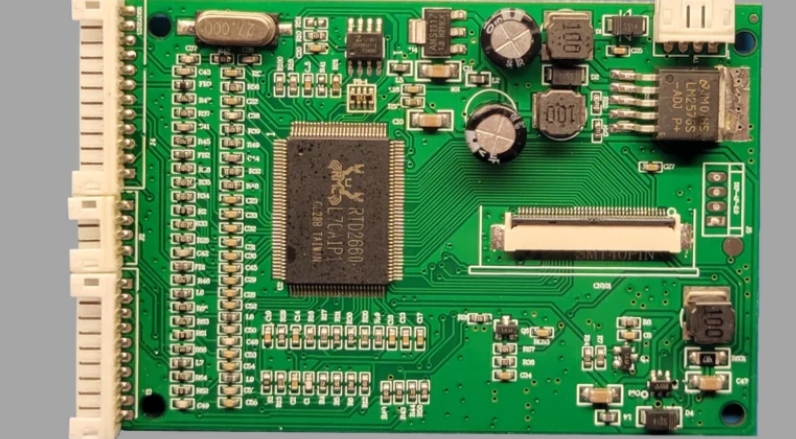
The green driver board isn't availbale anymore. No information or refernce came with my purchase of it, just what is listed on the site's description.
The green has more pads/pins to connect to as oppose to the blue driver board.
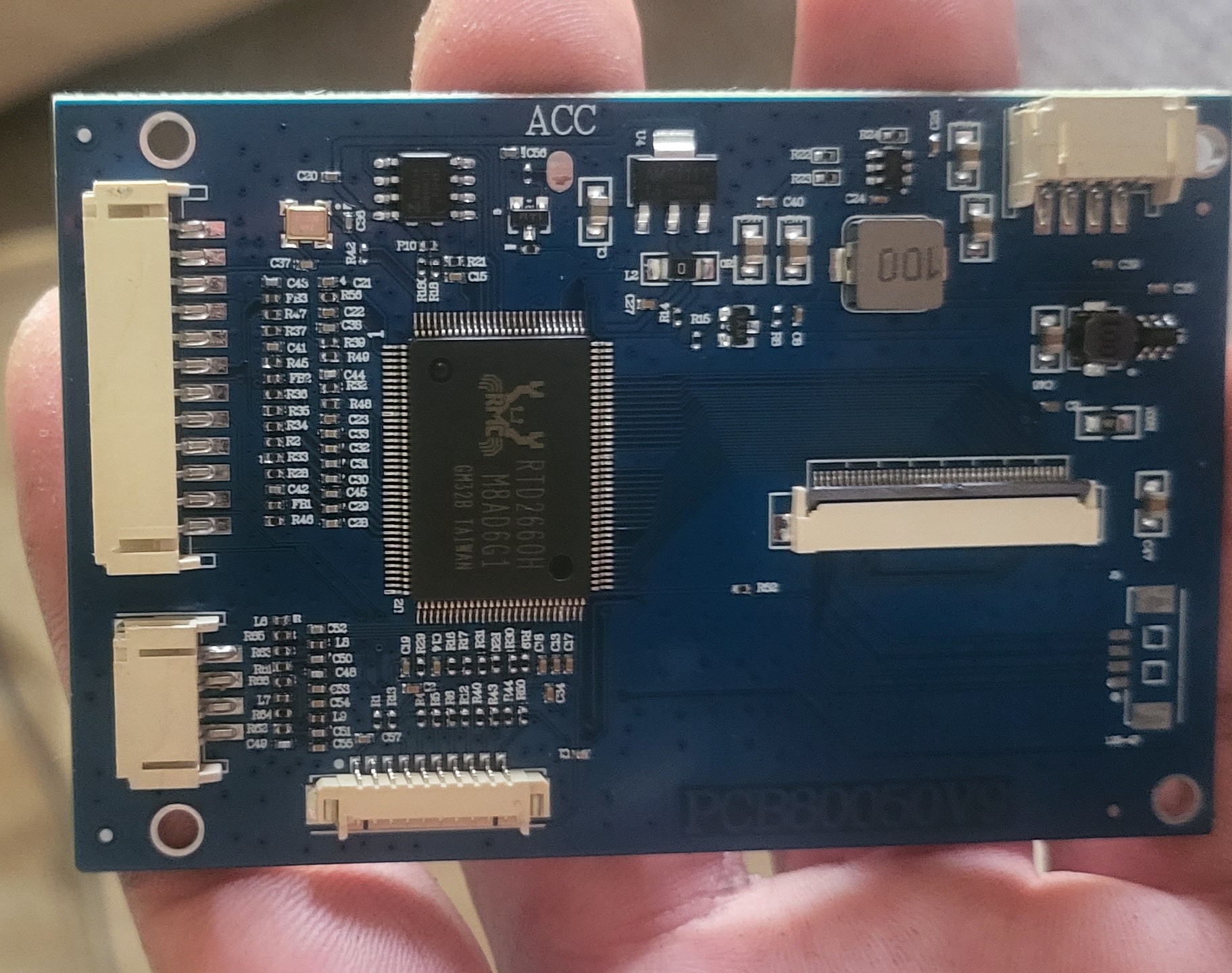
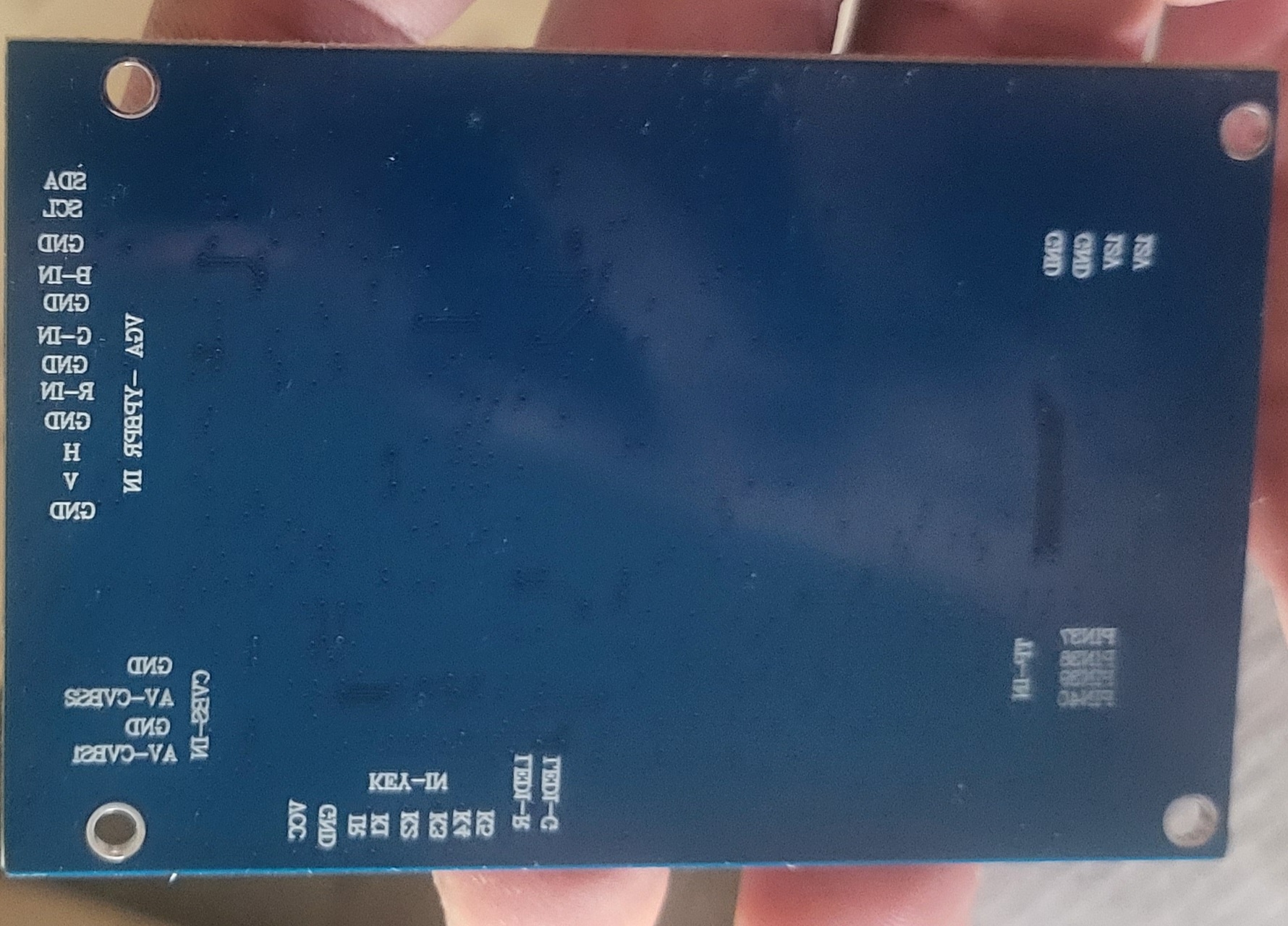
The labels on back of the blue driver board. I don't know what labels are are the back of the green driver board.
I was using the Ginger of oz Ashida build video as one of the references for building a Ashida.
Around the 7:10:50 mark of video he begins to connect the two lines to use the 2 bottom buttons to the green driver board.
Earlier he decided that he wanted to be able to run auto config and wasn't going to use bluetooth and repurpoe it.
He cut the race to the Sync pad from the 3.3v line and grounded it. That was one of the two
wires he ran to the vidoe driver board.
I don't planon using bluetooth either and wanted to be able to utilize it for another purpse similar to
what Ginger did. I really curious if this is possible for the blue driver board.
Thanks
.
The green driver board isn't availbale anymore. No information or refernce came with my purchase of it, just what is listed on the site's description.
The green has more pads/pins to connect to as oppose to the blue driver board.
The labels on back of the blue driver board. I don't know what labels are are the back of the green driver board.
I was using the Ginger of oz Ashida build video as one of the references for building a Ashida.
Around the 7:10:50 mark of video he begins to connect the two lines to use the 2 bottom buttons to the green driver board.
Earlier he decided that he wanted to be able to run auto config and wasn't going to use bluetooth and repurpoe it.
He cut the race to the Sync pad from the 3.3v line and grounded it. That was one of the two
wires he ran to the vidoe driver board.
I don't planon using bluetooth either and wanted to be able to utilize it for another purpse similar to
what Ginger did. I really curious if this is possible for the blue driver board.
Thanks
.