
- Joined
- Apr 15, 2018
- Messages
- 48
- Likes
- 80
Hey everyone!
Sorry for being MIA for so long, but I return with tasty memes.
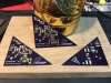
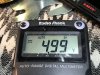
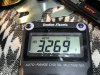
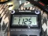
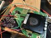
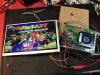
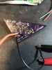
I present to you all: PIIza TIme. A custom Wii regulator board built off of 2x TPS54395 switching voltage regulators with around ~90%-95% on the 5.0v and 3.3v lines and ~80%-85% efficiency on the 1.15v and 1.0v lines. Also has a pad that can brought high or low to turn on/off the regulator board with a 2 position switch.
I started this project after MGC last year as my first ever PCB design project. After two boards that were garbage, some help from @Gman ( u baber), and many butt tears, I finally have a design that kicks ass.
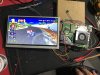
The name is broken into two parts "PIIza" because it's shaped like a slice o' pizza and fits perfectly in with an "OMGWTF" trim to complete the rectangle it almost makes. It's also a shout out to @Aurelio because he is a badass piiza man, thanks for all your work man! "TIme" because it's built off of a TI regulator.
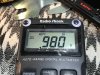
PIIza TIme does get pretty hot, but unfortunately I don't have a FLIR or even a thermocouple to test exactly how hot. In my testing it did not seem to affect performance of the regulators but I would recommend putting some type of small heatsink on top of the chips. Doesn't have to be fancy, something small would do with a little thermal pad would do. Raspberry pi heatsinks would do nicely.
There are two options on how to get your filthy mitts on this board:
1. If I can get people to commit to at least 10 boards all together, I will be selling them at $30 a piece + shipping (around $3 in the US, $10 international). Just gotta hit the 10 board mark to make it worth the time required for assembly.
2. Make your own, the design is now open source for BitBuilt to do as they please. Files + BOM in my github here:
https://github.com/PostmanMods/PIIza-TIme
I got the design practice I wanted out of this project so I release it into the world for people to do as they please with it. All I ask is if you use it just throw me the credit for the design if you use it in your design.
I hope to see this in portables ASAP! Let me know below if you are interested, just leave your username, the desired quantity, and whether you are US or international:
Sorry for being MIA for so long, but I return with tasty memes.
I present to you all: PIIza TIme. A custom Wii regulator board built off of 2x TPS54395 switching voltage regulators with around ~90%-95% on the 5.0v and 3.3v lines and ~80%-85% efficiency on the 1.15v and 1.0v lines. Also has a pad that can brought high or low to turn on/off the regulator board with a 2 position switch.
I started this project after MGC last year as my first ever PCB design project. After two boards that were garbage, some help from @Gman (
u baber), and many butt tears, I finally have a design that kicks ass.The name is broken into two parts "PIIza" because it's shaped like a slice o' pizza and fits perfectly in with an "OMGWTF" trim to complete the rectangle it almost makes. It's also a shout out to @Aurelio because he is a badass piiza man, thanks for all your work man! "TIme" because it's built off of a TI regulator.
PIIza TIme does get pretty hot, but unfortunately I don't have a FLIR or even a thermocouple to test exactly how hot. In my testing it did not seem to affect performance of the regulators but I would recommend putting some type of small heatsink on top of the chips. Doesn't have to be fancy, something small would do with a little thermal pad would do. Raspberry pi heatsinks would do nicely.
There are two options on how to get your filthy mitts on this board:
1. If I can get people to commit to at least 10 boards all together, I will be selling them at $30 a piece + shipping (around $3 in the US, $10 international). Just gotta hit the 10 board mark to make it worth the time required for assembly.
2. Make your own, the design is now open source for BitBuilt to do as they please. Files + BOM in my github here:
https://github.com/PostmanMods/PIIza-TIme
I got the design practice I wanted out of this project so I release it into the world for people to do as they please with it. All I ask is if you use it just throw me the credit for the design if you use it in your design.
I hope to see this in portables ASAP! Let me know below if you are interested, just leave your username, the desired quantity, and whether you are US or international:
Attachments
-
 2.2 MB Views: 538
Last edited:
