Worklog Raspberry Pi5 GameCube

MJMT

.
Joined
Apr 16, 2021
Messages
100
Likes
132
Portables
2
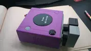
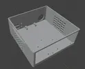
I'm always wanting to create yet another mini GameCube. It looks like games are more playable in the latest updates so I'm using a raspberry pi 5 with a M.2 Hat+ and a Mayflash GC controller adapter. Hopefully making this thread will give me motivation to show regular progress.
IMG_20251227_141755548.webp


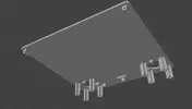
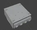
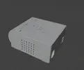
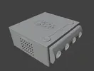
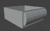
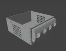
Update 01/03/26 17:36 EST - Working on the lid and minor details here and there. I'll add screw pints in the rear and tabs in the front. The Raspberry Pi logo is a trimmed down version of Lammesky's from Printables https://www.printables.com/model/14260-raspberry-pi-logo-fixed/files
https://www.printables.com/@Lammesky
Gamecube010326.webp


01/04/26 21:52 Zip folder added with STL models and images. I submitted the parts to be printed at PCBway. Going with orange for the case itself.

01/11/26 08:25 I have attached the PCB files as "PiCube.zip"

01/24/26 22:10 I have attached an updated zip file with the new models, new PCB, and a Lazy BoM of sorts
IMG_20260210_190650644.webp
 

Attachments

  • Gamecube Case 01.webp
    Gamecube Case 01.webp
    124.8 KB · Views: 26
  • GamecubeCSE122825.webp
    GamecubeCSE122825.webp
    283.3 KB · Views: 27
  • Raspberry pi5 Gamecube MMT.zip
    Raspberry pi5 Gamecube MMT.zip
    8 MB · Views: 19
Last edited:
Eugh.......... dirty emulation.............................

I am interested to see how this works though. Good luck!
 
Eugh.......... dirty emulation.............................

I am interested to see how this works though. Good luck!
Well, I finished the wii trim version years ago. Shoved it inside the Brook adapter.
 

Attachments

  • 17668856947626246383106700875841.webp
    17668856947626246383106700875841.webp
    428.9 KB · Views: 24
Parts ordered... I'm going to try to get away with as little soldering as possible on this one. I'll be trying to add a top power switch and P-LED. I have a few from computer cases I might try. If I can program a "reset" button to return to the main Batocera menu, that will be a nice bonus. Pretty sure you can since an SNES/NES controller can be wired directly to a PI with a little bit of programming. I know it wouldn't be that useful since you can do that from your controller as is but- reset buttons are cool.

AmazonParts.webp
 
Here's a small update on the 3D model. Going away for the rest of the week. I'm wondering if I should make a little PCB with an NES controller chip for my reset button. That might be pretty silly.
IMG_20251230_200021762.webp
 
I think I've finished with the Model. I'll convert it into individual STLs and try to link it later tonight. - Added the file to the OG post. I'll be designing 2 PCBs for this next to be fabricated. Will need to add the coding for a power LED and for the NES controller next.
 

Attachments

  • Top Case.webp
    Top Case.webp
    172.4 KB · Views: 23
  • Inserts.webp
    Inserts.webp
    181.2 KB · Views: 24
  • Ports Rear.webp
    Ports Rear.webp
    92.7 KB · Views: 15
  • Ports Front.webp
    Ports Front.webp
    150.3 KB · Views: 18
  • Bottom Case.webp
    Bottom Case.webp
    178.9 KB · Views: 18
  • Bottom.webp
    Bottom.webp
    83.4 KB · Views: 22
  • Back Right.webp
    Back Right.webp
    169 KB · Views: 17
  • Front Left.webp
    Front Left.webp
    233.8 KB · Views: 18
Last edited:
**I have created and ordered this PCB from OSH Park. I guess I'll try to do the LED and GPIO program updates while I wait and cross my fingers while waiting for everything to arrive.
PiCubePCB.webp


Welp, Gemini said that I have to connect all of the unused buttons to a resistor so they register as not being pushed so I will do a modification to mine and I'll change this board layout be fore releasing it.


**Update- apparently you don't use a shift register with a raspberry pi 5 because they updated their IO controller to an RP1 which doesn't understand shift registers. You have to use program code with Triggerhappy to grab button presses on the GPIO and translate it to keystrokes and such. I have updated the board to have no shift register.
PCB picture.webp
 
Last edited:
Drilled these holes tonight and the board still works. I destroyed the 1st one days ago
IMG_20260117_193154277.webp
 
Here's the exciting conclusion. This one is all resin from JLCPCB. Unfortunately, the enclosure could have used about 5 more mm in height. It's just a bit too tight. The length could probably use about 3mm as well. F-Zero's performance was also a bit sub-par still. This GameCube adapter is also a bit too cheap as well. You sometimes need to toggle it's switch to get it to be detected. At this time- I'd either use a more expensive mini PC or just do a Wii trim to make it better.
IMG_20260209_121251290.webp
IMG_20260209_155505852.webp
IMG_20260209_162028829.webp
IMG_20260209_162304251.webp
IMG_20260209_164226497.webp
 
Back
Top