
You are using an out of date browser. It may not display this or other websites correctly.
You should upgrade or use an alternative browser.
You should upgrade or use an alternative browser.
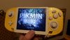
Worklog G-Wii Yellow
- Thread starter CalebPikmin
- Start date
- Joined
- Apr 12, 2020
- Messages
- 207
- Likes
- 236
This log is like having a first child for me. You can't have enough pictures lol!This is the amount of pictures we all should be striving to upload on our worklogs
- Joined
- Apr 12, 2020
- Messages
- 207
- Likes
- 236
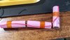
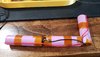
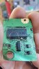
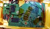
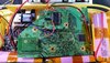
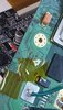
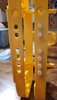
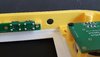
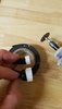
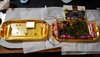
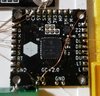
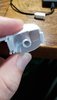
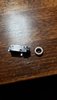
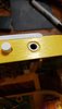
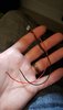
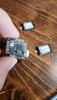
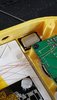
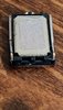
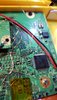
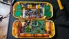
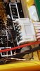
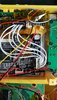
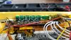
Batteries all wired up proper like and MX chip complete! The USB data lines kicked my butt lol.
I also wanted to try screwing the MX to the Wii post instead of using hot glue. We shall see how it pans out!
I also wanted to try screwing the MX to the Wii post instead of using hot glue. We shall see how it pans out!
Attachments
-
 20210916_112025.jpg3.4 MB · Views: 417
 -
 20210916_112632.jpg1.2 MB · Views: 408
 -
 20210916_115757.jpg2.9 MB · Views: 402
 -
 20210916_133440.jpg3 MB · Views: 423
 -
 20210916_171044.jpg1.2 MB · Views: 402
 -
 20210916_202933.jpg951.4 KB · Views: 416
 -
 20210916_211930.jpg3.4 MB · Views: 389
 -
 20210916_212618.jpg2.8 MB · Views: 397
 -
 20210916_224616.jpg3.9 MB · Views: 406
I really like this idea!I also wanted to try screwing the MX to the Wii post instead of using hot glue.
- Joined
- Jul 9, 2020
- Messages
- 230
- Likes
- 501
Great job buddy! I've been only following this through our DMs... its cool to see the whole log here for the first time. You are rocking it... this is gonna be really beautiful with the yellow and white.
Are you thinking about custom buttons? or just standard colors?
Keep crushing bro!
(testing then more crushing) ;P
Are you thinking about custom buttons? or just standard colors?
Keep crushing bro!
(testing then more crushing) ;P
- Joined
- Apr 12, 2020
- Messages
- 207
- Likes
- 236
Great job buddy! I've been only following this through our DMs... its cool to see the whole log here for the first time. You are rocking it... this is gonna be really beautiful with the yellow and white.
Are you thinking about custom buttons? or just standard colors?
Keep crushing bro!
(testing then more crushing) ;P
Thanks man! And I really appreciate the support.
So I have all the gamecube buttons (standard) in white already and I have all the video buttons in white (caps I need to glue on each tact switch) as well. I have a small surprise coming up with the case as well... but I think I'll save that for when this thing is finally complete hehe.
I for sure plan on everything follow the white and yellow theme!
- Joined
- Apr 12, 2020
- Messages
- 207
- Likes
- 236
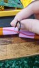
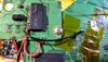
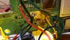
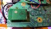
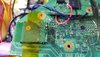
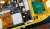
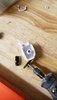
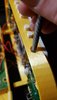
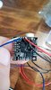
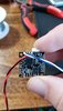
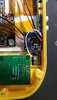
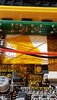
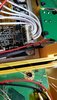
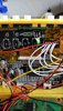
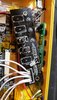
Alright... so turns out the screw was grounding and touching the 3.3v and possibly causing pressure on the U10 wire. I was getting SCREWED! Get it?! So I just went to the trusty hot glue lol...
I may in the future try the screw again but if I do.. I would only do so before running anything through that screw post and the wire under the MX chip (voltage point under the MX).
But for now. Fixed the MX and completed the Bluetooth 3.3v and ground") . More to come tomorrow!
. More to come tomorrow!
Edit: Bluetooth complete!
Another edit:
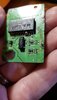
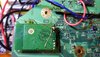
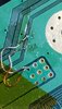
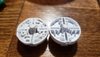
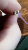
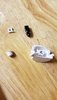
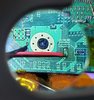
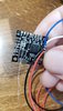
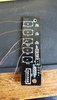
@SparkleBear noticed a bridged connection on the Bluetooth. So I redid the connection and did a continuity test and made sure nothing was shorting with the multimeter. It's hard to get a picture of it being so small but here's my best shot! Also the picture doesn't do it justice but I promise its not shorting on the ground board anymore (or to each other)!
I may in the future try the screw again but if I do.. I would only do so before running anything through that screw post and the wire under the MX chip (voltage point under the MX).
But for now. Fixed the MX and completed the Bluetooth 3.3v and ground
. More to come tomorrow!Edit: Bluetooth complete!
Another edit:
@SparkleBear noticed a bridged connection on the Bluetooth. So I redid the connection and did a continuity test and made sure nothing was shorting with the multimeter. It's hard to get a picture of it being so small but here's my best shot! Also the picture doesn't do it justice but I promise its not shorting on the ground board anymore (or to each other)!
Attachments
Last edited:
Nice job! Really awesome seeing all your progress and especially all the picture documentation. Can’t to see the final product!Alright... so turns out the screw was grounding and touching the 3.3v and possibly causing pressure on the U10 wire. I was getting SCREWED! Get it?! So I just went to the trusty hot glue lol...
I may in the future try the screw again but if I do.. I would only do so before running anything through that screw post and the wire under the MX chip (voltage point under the MX).
But for now. Fixed the MX and completed the Bluetooth 3.3v and ground
Edit: Bluetooth complete!
- Joined
- Apr 12, 2020
- Messages
- 207
- Likes
- 236
- Joined
- Apr 12, 2020
- Messages
- 207
- Likes
- 236
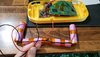
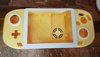
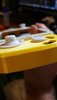
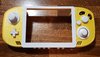
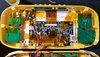
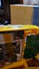
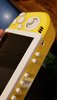
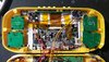
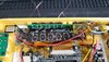
Update and picture DUMP time!
Got a new rev 2 case printed by @Gman
Also huge thanks for @Wesk
for putting together the cool design on the back (will be revealed on the final post)!
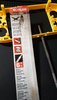
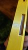
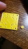
So.. I used liquid super glue for the new case. I used a better method of expanding the video holes by using a filing tool I bought from home depot. So much better than the drill bit method.
Updated to rev 1.3 of bbloader so my temp is no longer showing negative.
Started messing with the break out boards from @Ethan
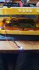
Spray painted the edge of the heat sink and did a clear coat with high heat spray paint (made for a grill LOL)
Worker with the buttons and got a ton of amazing advice from @SparkleBear
Seriously thank you man! I got the A & B button just right after using multiple techniques. I also used electrical tape taped around the buttons to give me something to hold on to while cutting and sanding. I ended up sanding to much but glued a thin metal washer to make it work!! Also used my dremel to cut down the middle a bit for the A button because after the screwing down the breakout it was giving me a hard time haha.
Glued the left and right triggers and soldered magnet wire before transferring everything from the previous case to the new one.
X and Y button next and then wiring up all the buttons to the GC+! Then audio (modified the breakout board so the audio board works with it) and then on to switching and doing wiring from composite to VGA. And then closing up and then done! Woooo!!
Got a new rev 2 case printed by @Gman
Also huge thanks for @Wesk
for putting together the cool design on the back (will be revealed on the final post)!
So.. I used liquid super glue for the new case. I used a better method of expanding the video holes by using a filing tool I bought from home depot. So much better than the drill bit method.
Updated to rev 1.3 of bbloader so my temp is no longer showing negative.
Started messing with the break out boards from @Ethan
Spray painted the edge of the heat sink and did a clear coat with high heat spray paint (made for a grill LOL)
Worker with the buttons and got a ton of amazing advice from @SparkleBear
Seriously thank you man! I got the A & B button just right after using multiple techniques. I also used electrical tape taped around the buttons to give me something to hold on to while cutting and sanding. I ended up sanding to much but glued a thin metal washer to make it work!! Also used my dremel to cut down the middle a bit for the A button because after the screwing down the breakout it was giving me a hard time haha.
Glued the left and right triggers and soldered magnet wire before transferring everything from the previous case to the new one.
X and Y button next and then wiring up all the buttons to the GC+! Then audio (modified the breakout board so the audio board works with it) and then on to switching and doing wiring from composite to VGA. And then closing up and then done! Woooo!!
Attachments
-
 20210924_231839.jpg864.1 KB · Views: 354
 -
 20210924_231926.jpg860.6 KB · Views: 361
 -
 20210924_225726.jpg1.2 MB · Views: 360
 -
 20210925_155147.jpg2.6 MB · Views: 381
 -
 20210925_152907.jpg1.5 MB · Views: 391
 -
 20210927_172706.jpg3.1 MB · Views: 379
 -
 20210927_174014.jpg3.4 MB · Views: 388
 -
 20210928_173540.jpg3.5 MB · Views: 403
 -
 20210928_181606.jpg864.8 KB · Views: 370
 -
 20210928_213345.jpg776.2 KB · Views: 346
 -
 20210928_194213.jpg1.1 MB · Views: 334
 -
 20210928_194219.jpg919.3 KB · Views: 345
 -
 20210928_211944.jpg1 MB · Views: 344
 -
 20210928_211950.jpg1.2 MB · Views: 353
 -
 20210928_212142.jpg973.1 KB · Views: 335
 -
 20211001_172707.jpg1.8 MB · Views: 348
 -
 20211001_190402.jpg2.4 MB · Views: 329
 -
 20211001_210234.jpg1.1 MB · Views: 329
 -
 20211001_210811.jpg769.7 KB · Views: 343
 -
 20211001_212901.jpg712.5 KB · Views: 310
 -
 20211001_234813.jpg607.1 KB · Views: 319
 -
 20211001_234826.jpg763.5 KB · Views: 331
 -
 20211001_234834.jpg875.5 KB · Views: 320
 -
 20211001_234843.jpg659.6 KB · Views: 311
 -
 20211002_000815.jpg3.1 MB · Views: 344
 -
 20211002_003002.jpg3 MB · Views: 378
 -
 20211002_013858.jpg2.5 MB · Views: 383
Wow the color scheme looks so good - i never thought i'd see a white c stick and be so turned on lol keep up the good work man!
- Joined
- Apr 12, 2020
- Messages
- 207
- Likes
- 236
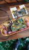
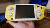
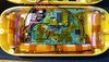
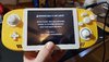
Update time!!!!
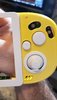
Got all my buttons working super good. GC+ board wired up. I had to do a lot of interesting things to get the buttons feeling right.. such as putting small peices of cut rubber from other controller pads in places.. mainly on the down d-pad and the B button. I completely forgot about the start button.. so I did that in a hurry lol..
I also had to use washers on the A and B buttons so I ended up spray painting the edges white on the circle washers. It was halarious.
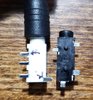
So then I wanted to start on the audio.. I reached out to @SparkleBear because he is a baller shock collar. And he told me the headphone socket i ordered was "closed circuit" and would'nt work *cry*... and SO! This would not deter me from getting my white and yellow esthetic!
I took a gamecube R button and smashed that black socket (open circuit) in there! What do you know?! It fit almost perfect! So then the plan was in place! I would slowly sand away the socket hole and sanded the cut off tube from the "L" gamecube button. I chose the L button because obviously I'm not giving up my Button Rights for this build! I feel that I can do what I want with my portable body! #G-WiiRights
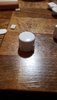
Gluded the sanded socket peices together and boom! Good to go!
Anyways... all jokes aside. Tested my Bluetooth relocation finally and BAM!
Also the hottest my portable gets is 51°c. Played it for an hour and it's so freaking cool!
Side note:
I had an issue with my 3v3 on the GC+ shorting when both halves were closed up. I ended up cleaning with ISO and then taping carefully to make sure nothing touched and that seemed to fix my issue with reseting randomly lol.
Hope this helps someone! Thanks for reading!
Got all my buttons working super good. GC+ board wired up. I had to do a lot of interesting things to get the buttons feeling right.. such as putting small peices of cut rubber from other controller pads in places.. mainly on the down d-pad and the B button. I completely forgot about the start button.. so I did that in a hurry lol..
I also had to use washers on the A and B buttons so I ended up spray painting the edges white on the circle washers. It was halarious.
So then I wanted to start on the audio.. I reached out to @SparkleBear because he is a baller shock collar. And he told me the headphone socket i ordered was "closed circuit" and would'nt work *cry*... and SO! This would not deter me from getting my white and yellow esthetic!
I took a gamecube R button and smashed that black socket (open circuit) in there! What do you know?! It fit almost perfect! So then the plan was in place! I would slowly sand away the socket hole and sanded the cut off tube from the "L" gamecube button. I chose the L button because obviously I'm not giving up my Button Rights for this build! I feel that I can do what I want with my portable body! #G-WiiRights
Gluded the sanded socket peices together and boom! Good to go!
Anyways... all jokes aside. Tested my Bluetooth relocation finally and BAM!
Also the hottest my portable gets is 51°c. Played it for an hour and it's so freaking cool!
Side note:
I had an issue with my 3v3 on the GC+ shorting when both halves were closed up. I ended up cleaning with ISO and then taping carefully to make sure nothing touched and that seemed to fix my issue with reseting randomly lol.
Hope this helps someone! Thanks for reading!
Attachments
-
 20211007_174355.jpg3.3 MB · Views: 357
 -
 20211007_212258.jpg488.8 KB · Views: 391
 -
 20211009_212756.jpg3.4 MB · Views: 346
 -
 20211009_212751.jpg3.2 MB · Views: 367
 -
 20211010_205753.jpg818.2 KB · Views: 330
 -
 20211010_205800.jpg840 KB · Views: 319
 -
 20211011_180056.jpg928.5 KB · Views: 317
 -
 20211011_181326.jpg387.2 KB · Views: 323
 -
 20211011_183331.jpg3.2 MB · Views: 314
 -
 20211011_184202.jpg686.3 KB · Views: 298
 -
 20211011_184345.jpg1.5 MB · Views: 332
 -
 20211011_184815.jpg514.4 KB · Views: 308
 -
 20211011_184316.jpg1.4 MB · Views: 317
 -
 20211011_185614.jpg1.1 MB · Views: 296
 -
 20211011_185652.jpg633.2 KB · Views: 317
 -
 20211011_192427.jpg1 MB · Views: 302
 -
 20211011_192818.jpg965.4 KB · Views: 293
 -
 20211011_191606.jpg1.1 MB · Views: 306
 -
 20211011_194723.jpg822.9 KB · Views: 301
 -
 20211011_200417.jpg995.4 KB · Views: 311
 -
 20211011_203419.jpg914.5 KB · Views: 332
 -
 20211011_203433.jpg842.9 KB · Views: 311
 -
 20211011_203426.jpg1.1 MB · Views: 317
 -
 20211011_205114.jpg689.1 KB · Views: 339
 -
 20211009_212644.jpg2.9 MB · Views: 338
Last edited:
- Joined
- Apr 12, 2020
- Messages
- 207
- Likes
- 236
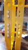
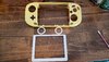
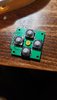
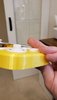
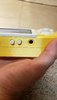
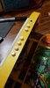
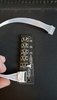
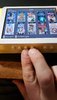
Those are going to be the video LCD controls and volume controls. I still need to do those heh...Quick question, the buttons at the bottom. What use Will you give them?
Evilemi
.
- Joined
- Aug 28, 2021
- Messages
- 42
- Likes
- 35
Oh I see, I thought those were start, select, restart or some sort. Any plans for adding these?Those are going to be the video LCD controls and volume controls. I still need to do those heh...
- Joined
- Apr 12, 2020
- Messages
- 207
- Likes
- 236
Well I have the start button on top beside the power. For restart I feel like powering off and on should be fine and then select I think the A button does the same thing.. hmmmOh I see, I thought those were start, select, restart or some sort. Any plans for adding these?
So I still need to figure out what LCD controls I want. Or if I want anymore GC+ buttons on the bottom (I think a duplicate Start button would be the only thing left... I was under the impression after testing the 2 "S" pads on GC+ it seemed to be connected with multimeter continuity wise)...
More updates to come though!
- Joined
- Apr 12, 2020
- Messages
- 207
- Likes
- 236
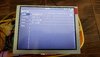
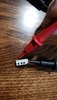
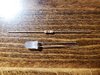
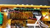
Update! Completed the LED! Used a standard white LED (had issues with the other). Had to do some troubleshooting and @Gman helped me figure out my polarity was flipped! He told me I could test with 3v3 connected to positive and a ground test point on the Wii. It worked! So I connected the negative to the A (PMS connection) and then the positive to the L (PMS connection) Boom all set and functional now!
Side note: I used a 2k resistor instead of a 1k so its a little dimmer. Which I kind of like to be honest! Not too bright in the dark and all that jazz!
Hoping to finally do the audio on this now that it's about to be Thanksgiving break (I keep saying that... but I mean it this time)! Lol
Side note: I used a 2k resistor instead of a 1k so its a little dimmer. Which I kind of like to be honest! Not too bright in the dark and all that jazz!
Hoping to finally do the audio on this now that it's about to be Thanksgiving break (I keep saying that... but I mean it this time)! Lol
Attachments

- Joined
- Apr 12, 2020
- Messages
- 207
- Likes
- 236
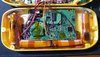
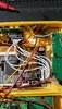
Audio complete! Headphones and both speakers working properly! Had some confusion with finding the 1v8 but @Gman pointed out the TP2 connection on the Wii being a good 1v8 point to solder to!
Also big shout to @SparkleBear for helping me figure out the wiring for the buttons on the bottom (instead of the hud). I think overall this is a good route. And I think it made it more simplistic!
Last step now is VGA and then the big reveal!
Note:
Used some hot glue to nail down the speakers and provide more structure to the mounted headphone jack. Hoping it will work out!
Attachments
-
 20211121_230611.jpg3.5 MB · Views: 333
 -
 20211121_141555.jpg1.3 MB · Views: 308
 -
 20211121_142252.jpg834.4 KB · Views: 274
 -
 20211121_145145.jpg1.1 MB · Views: 271
 -
 20211121_141655.jpg935.3 KB · Views: 285
 -
 20211121_151750.jpg1,018.4 KB · Views: 275
 -
 20211121_152220.jpg990.4 KB · Views: 269
 -
 20211121_180658.jpg1.4 MB · Views: 311
 -
 20211121_180645.jpg1.5 MB · Views: 280
 -
 20211121_230604.jpg1.2 MB · Views: 274
 -
 20211121_230619.jpg3.5 MB · Views: 278
 -
 20211121_230615.jpg3.4 MB · Views: 287
 -
 20211121_230611.jpg3.5 MB · Views: 289
- Joined
- Apr 12, 2020
- Messages
- 207
- Likes
- 236
Alright!
So small update but took a ton of time today.
Honesty, I just need to shout out:
@Cyframe @Gman @Ethan @SparkleBear for bearing with my constant (wanted or unwanted) messaging lol! I can be a bit much when panicking! Sorry guys but also thank you for helping!
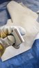
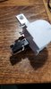
So I needed a better mounting support for my headphone jack so I superglued as I pushed in the jack this time and cut up a couple forward facing extra printed button boards to push against the backside of the socket as a headphone is pushed in. So no more pushing in the socket when plugging in headphones!
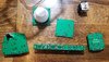
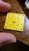
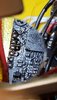
The big time suck today was when I soldered up the video button board. I got some amazing breakout boards from Ethan/Pickles but unfortunately my board was a little different in terms of resistance/resistors. Thanks Ethan for helping me out of that Pickle! I still had to wire up the black PCB button board to the driver LCD. But no sweat!
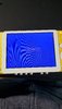
I naturally soldered the video cable from the LCD to the driver control board in reverse direction to help increase my anxiety! Luckily G-Man just simply suggested some quick troubleshooting steps and to try soldering the cables in the opposite direction to see if it works.
So 1 went to 6 and 2 went to 5 and so on. Seemed odd but it worked!
Also Cyframe helped me think logically and just suggested soldering a couple tact switches back on to help test quick before trying the breakout board to the tact switches on the green board. Which helped out a ton.
I did a resistance test which helped me understand where I started and ended because of Sparkly the best Bear on the planet.
Pro tips though:
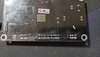
1. Always take pictures of front and back of your boards. It took me a second to find the backside of the LCD. But its a huge help!
2. Try not to panic and message/ping everyone around a Holiday lol!! Love y'all!
P.S. The G-Wii was a huge hit at the Thanksgiving party. Had a uncle, sister in law, brother in law/friends, brother, and dad test it out! They all loved it and had a bunch of good questions. Mainly wanting me to make them one... haha!
So small update but took a ton of time today.
Honesty, I just need to shout out:
@Cyframe @Gman @Ethan @SparkleBear for bearing with my constant (wanted or unwanted) messaging lol! I can be a bit much when panicking! Sorry guys but also thank you for helping!
So I needed a better mounting support for my headphone jack so I superglued as I pushed in the jack this time and cut up a couple forward facing extra printed button boards to push against the backside of the socket as a headphone is pushed in. So no more pushing in the socket when plugging in headphones!
The big time suck today was when I soldered up the video button board. I got some amazing breakout boards from Ethan/Pickles but unfortunately my board was a little different in terms of resistance/resistors. Thanks Ethan for helping me out of that Pickle! I still had to wire up the black PCB button board to the driver LCD. But no sweat!
I naturally soldered the video cable from the LCD to the driver control board in reverse direction to help increase my anxiety! Luckily G-Man just simply suggested some quick troubleshooting steps and to try soldering the cables in the opposite direction to see if it works.
So 1 went to 6 and 2 went to 5 and so on. Seemed odd but it worked!
Also Cyframe helped me think logically and just suggested soldering a couple tact switches back on to help test quick before trying the breakout board to the tact switches on the green board. Which helped out a ton.
I did a resistance test which helped me understand where I started and ended because of Sparkly the best Bear on the planet.
Pro tips though:
1. Always take pictures of front and back of your boards. It took me a second to find the backside of the LCD. But its a huge help!
2. Try not to panic and message/ping everyone around a Holiday lol!! Love y'all!
P.S. The G-Wii was a huge hit at the Thanksgiving party. Had a uncle, sister in law, brother in law/friends, brother, and dad test it out! They all loved it and had a bunch of good questions. Mainly wanting me to make them one... haha!
Attachments
-
 20211124_143139.jpg1.1 MB · Views: 294
 -
 20210915_102723.jpg2.7 MB · Views: 272
 -
 20211126_002527.jpg872.8 KB · Views: 256
 -
 20211126_002536.jpg750.7 KB · Views: 293
 -
 20211126_003115.jpg1.1 MB · Views: 285
 -
 20211126_114209.jpg1.3 MB · Views: 293
 -
 20211126_123315.jpg3.1 MB · Views: 271
 -
 20211126_131332.jpg1.6 MB · Views: 257
 -
 20211126_131349.jpg2.9 MB · Views: 285
 -
 20211126_132156.jpg1.3 MB · Views: 268
 -
 20211126_155752.jpg1.2 MB · Views: 272
 -
 20211126_160616.jpg1.4 MB · Views: 263
 -
 20211126_191833.jpg1.4 MB · Views: 269
 -
 20211126_205134.jpg1.3 MB · Views: 283
 -
 20211126_205126.jpg3.1 MB · Views: 287