Question Gboy build in progress

Joined
Oct 1, 2023
Messages
22
Likes
4
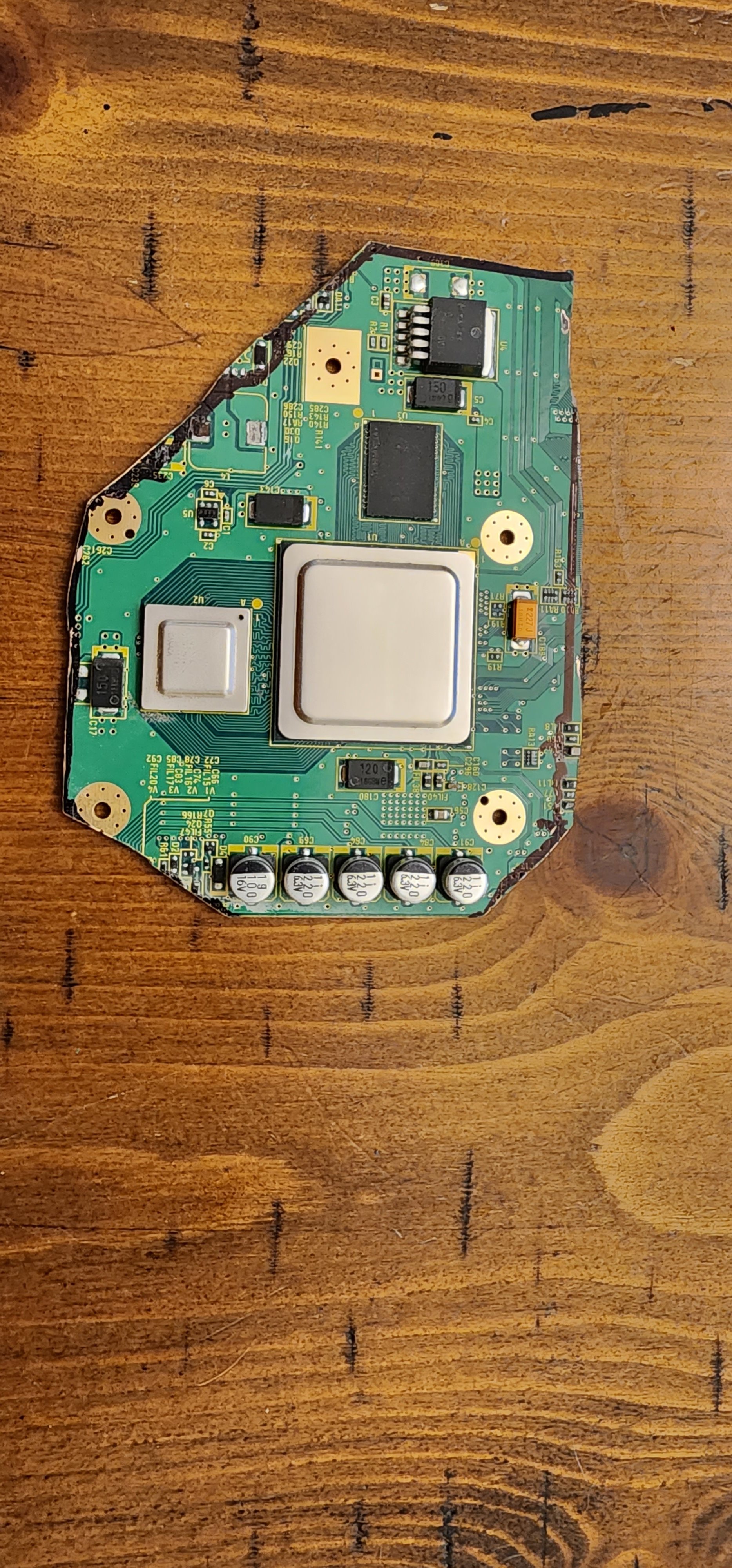
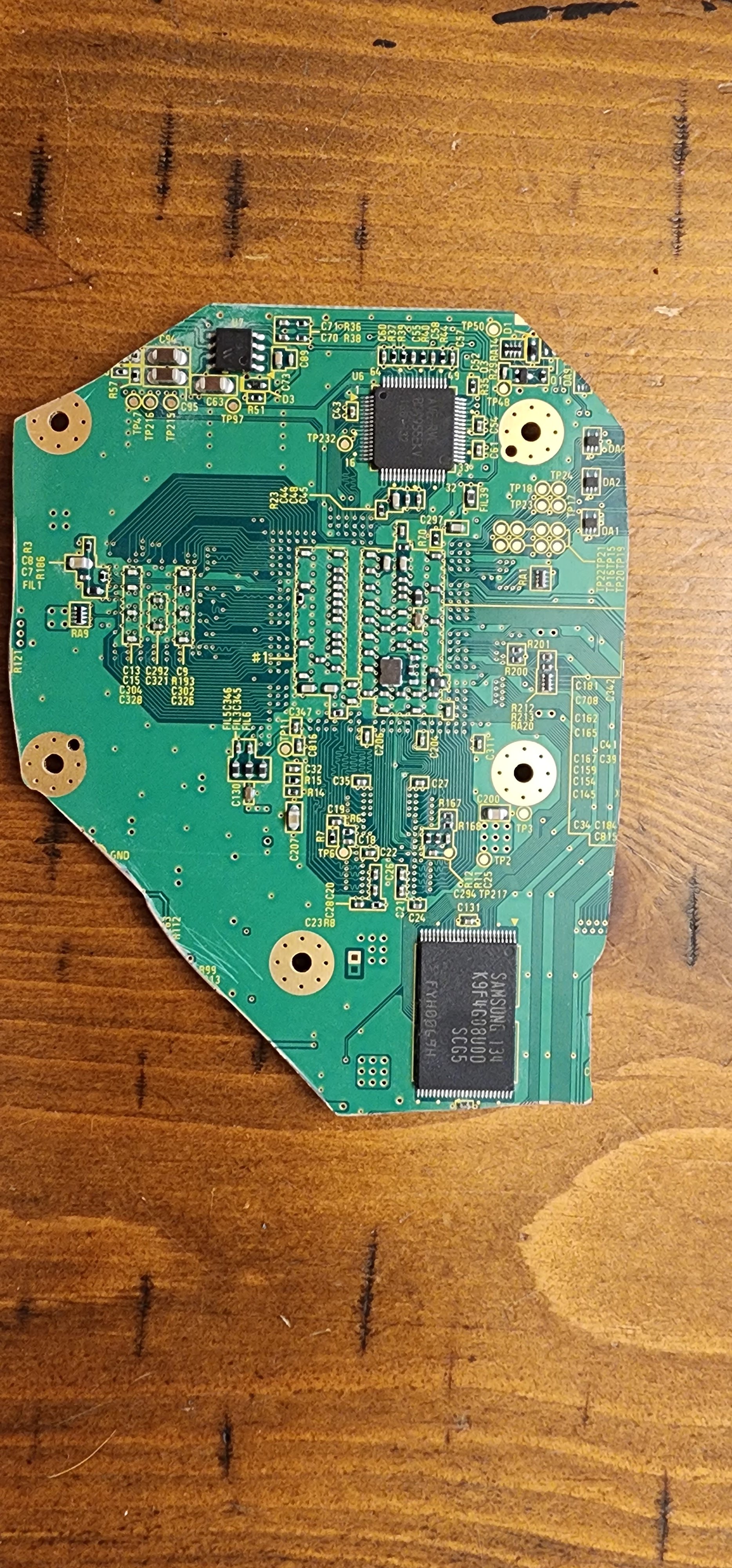
Hey guys, I've been researching for a few weeks and have just started on a gboy build. I've ordered all the necessary parts and I'm just waiting for everything to come in. I trimmed my motherboard today and I'm a little concerned about the trim. On the front of the motherboard in the top left corner there's a nic in the motherboard where the Dremel jumped a little. I just wanted to make sure this wasn't a problem and everything looked alright so far. Other than just having some soldering knowledge I'm very much a beginner as far as engineering goes and I'm not familiar enough with the wii mother board to know what everything does. Any advice would be greatly appreciated. Thank you guys!
20230930_224257.jpg
20230930_224305.jpg
 

Stitches

2 and a Half Dollarydoos
Staff member
.
.
Joined
Feb 5, 2017
Messages
3,848
Likes
3,025
Location
Banana Bender Land, Australia
Portables
6
That gouge looks fine, it's not near anything important. Looks like you've destroyed the right 3.3v filtering cap by the NAND tho
 
Joined
Oct 1, 2023
Messages
22
Likes
4
Do you mean this guy here? In the picture it looks like it's chopped off but it seems like it's still all there. I can get a better picture in a bit. If it's destroyed is there a way to fix that?
20230930_224305.jpg
 

Stitches

2 and a Half Dollarydoos
Staff member
.
.
Joined
Feb 5, 2017
Messages
3,848
Likes
3,025
Location
Banana Bender Land, Australia
Portables
6
Yeah that one. That capacitor and the vias that feed it are required for operation. If you haven't damaged the cap at all, then it should be okay. If you have damaged the cap, you'll want to relocate and replace it with another matching capacitor. I believe it's a 100nF capacitor, which you can find several donors for on the trimmed off part of the motherboard by checking the Wii Super Thread's capacitor list
 
Joined
Oct 1, 2023
Messages
22
Likes
4
Perfect! Thanks so much for the advice. Here's a better pic. Go me the cap looks like it's all there but I could be wrong. I kept the rest of the motherboard just in case so I will relocate another capacitor if necessary. Is there a chart that will show me what the resistance should be if I check it and also is there a guide or a walkthrough somewhere where someone else has done a similar relocation so I could see the process. Again I really appreciate your time and help.
20231001_083746.jpg
 
Joined
Oct 1, 2023
Messages
22
Likes
4
I think I read somewhere that double posting isn't allowed so I'm just updating my last post to give an update. I've made a lot of progress but hit a few snags too. I know the case looks rough but I'm currently living in an apartment and don't have a great area to sand and paint. I'll be moving early next year and plan to redo the case once I have more of an area to work around. I've got power working. Fan comes on and charging and USB file transfer both work. However I can't get the screen to come on. I wired 5v and ground to the screen, is there something further that needs to be wired to get the screen to turn on. This is the newer screen that I'm using so I didn't have to do a 5 v conversion just pulled off the old 5v plug.
20231024_150233.jpg
 
Last edited:
Top