
Question Audio R and L and power on a wii
- Thread starter xiuvx
- Start date
-
- Tags
- portable portablewii question wii
- Joined
- Nov 22, 2023
- Messages
- 36
- Likes
- 24
everything your heart desires is contained within
")
xiuvx
.
- Joined
- Dec 16, 2023
- Messages
- 26
- Likes
- 1
- Portables
- 1
Also I'm using a 12v battery with a dc cable slot which numbers on the points would I wire the dc cable to ? Sorry if I sound stupid I'm just very new to this kinda stuff also I have 1 cable going down from my car backup screen which I'm using and that wire is going from av1 which point number should I solder the wire to ?
If you're using a 12v lithium battery pack and you aren't using custom regulators, you must wire the battery pack to the Wii's 12v socket pins. The white slikscreen writing on the PCB will tell you which pin is positive and which is negative.Also I'm using a 12v battery with a dc cable slot which numbers on the points would I wire the dc cable to ? Sorry if I sound stupid I'm just very new to this kinda stuff also I have 1 cable going down from my car backup screen which I'm using and that wire is going from av1 which point number should I solder the wire to ?
You will also need to put a latching power switch between the battery pack and the Wii, due to the Wii having a "standby line" which provides constant power to a few parts of the system to allow for functionality like turning on the console using a Wiimote. If you don't have a separate switch to cut the power from the battery to the console and screen, the battery will slowly run out even while the system is "off".
xiuvx
.
- Joined
- Dec 16, 2023
- Messages
- 26
- Likes
- 1
- Portables
- 1
Also I already have a power switch attached to the battery do I need to wire on another one or is that one fine since it turns off the battery ?If you're using a 12v lithium battery pack and you aren't using custom regulators, you must wire the battery pack to the Wii's 12v socket pins. The white slikscreen writing on the PCB will tell you which pin is positive and which is negative.
You will also need to put a latching power switch between the battery pack and the Wii, due to the Wii having a "standby line" which provides constant power to a few parts of the system to allow for functionality like turning on the console using a Wiimote. If you don't have a separate switch to cut the power from the battery to the console and screen, the battery will slowly run out even while the system is "off".
If the battery already has a power switch then you're goodAlso I already have a power switch attached to the battery do I need to wire on another one or is that one fine since it turns off the battery ?
xiuvx
.
- Joined
- Dec 16, 2023
- Messages
- 26
- Likes
- 1
- Portables
- 1
Also one more question of the diagram thing that guy sent me it says that the other 12v point is only for ntsc consoles but I'm using a pal console what is the other 12v point on the wii motherboard ?If the battery already has a power switch then you're good
I think you've misunderstood the diagram. Voltage locations depend on whether the Wii is a 6 layer board or a 4 layer board, rather than the console's region. A console being NTSC or PAL pretty much only changes what the AVE chip sends to a few of the video data lines, and what disc regions a stock system will accept.Also one more question of the diagram thing that guy sent me it says that the other 12v point is only for ntsc consoles but I'm using a pal console what is the other 12v point on the wii motherboard ?
What board revision do you have? You can find the board revision by following this quick guide.
xiuvx
.
- Joined
- Dec 16, 2023
- Messages
- 26
- Likes
- 1
- Portables
- 1
Mines is a 4 layer board does that mean it would just completely match the 12v points on the diagram the other guy sent me ?I think you've misunderstood the diagram. Voltage locations depend on whether the Wii is a 6 layer board or a 4 layer board, rather than the console's region. A console being NTSC or PAL pretty much only changes what the AVE chip sends to a few of the video data lines, and what disc regions a stock system will accept.
What board revision do you have? You can find the board revision by following this quick guide.
Yes. All 4 layer Wiis have the same pinouts and voltage locations shown in the Trimming GuideMines is a 4 layer board does that mean it would just completely match the 12v points on the diagram the other guy sent me ?
xiuvx
.
- Joined
- Dec 16, 2023
- Messages
- 26
- Likes
- 1
- Portables
- 1
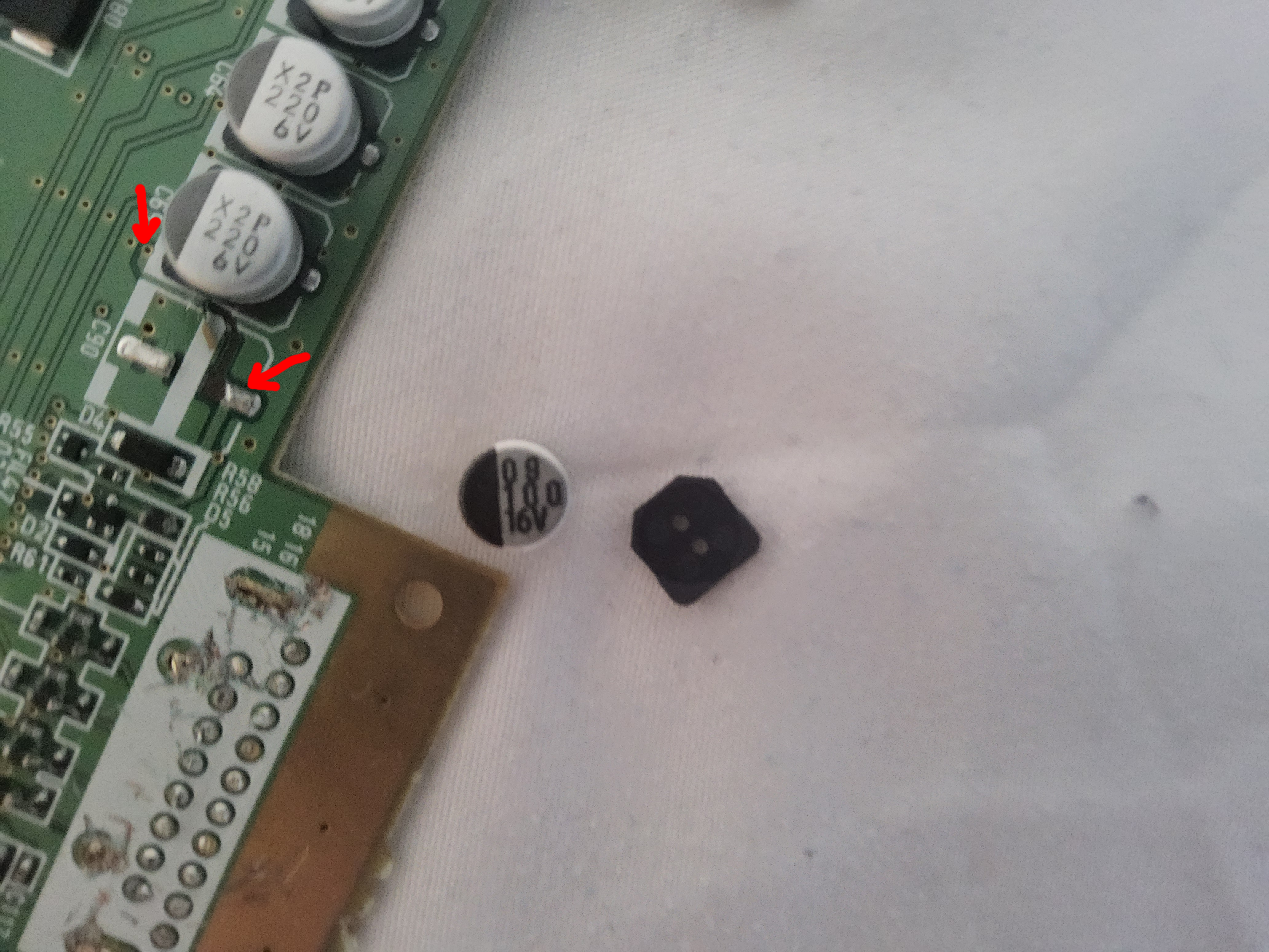
Hi me again I've just been removing the av out slot from the wii motherboard and I it was difficult desoldering it so I got some snips but with the snips I accidentally knocked the 16v capacitor and it fell off how do I resolder the capacitor as I have never resoldered a capacitor before thanksYes. All 4 layer Wiis have the same pinouts and voltage locations shown in the Trimming Guide
Photos pls
xiuvx
.
- Joined
- Dec 16, 2023
- Messages
- 26
- Likes
- 1
- Portables
- 1
Last edited:
IIRC that capacitor is for the sensor bar's 12v feed. The legs are torn off, so you can't easily reattach it, and you've severed the trace by ripping some of it out. You don't *need* to replace the filtering capacitor, but you do need to repair the trace by running a small wire between the two points shown. The point on the left is a 12v via. It's very small, so you may need to use a sharp knife to carefully scratch some green soldermask off the via to expose additional copper to solder to.
xiuvx
.
- Joined
- Dec 16, 2023
- Messages
- 26
- Likes
- 1
- Portables
- 1
Ok great thanks I got a little worried that I had broke it lolIIRC that capacitor is for the sensor bar's 12v feed. The legs are torn off, so you can't easily reattach it, and you've severed the trace by ripping some of it out. You don't *need* to replace the filtering capacitor, but you do need to repair the trace by running a small wire between the two points shown. The point on the left is a 12v via. It's very small, so you may need to use a sharp knife to carefully scratch some green soldermask off the via to expose additional copper to solder to.
View attachment 31219
Fortunately it's a simple fix