

Lazr
.
Idk how often I am going to post updates here.
Funky things are happening!!
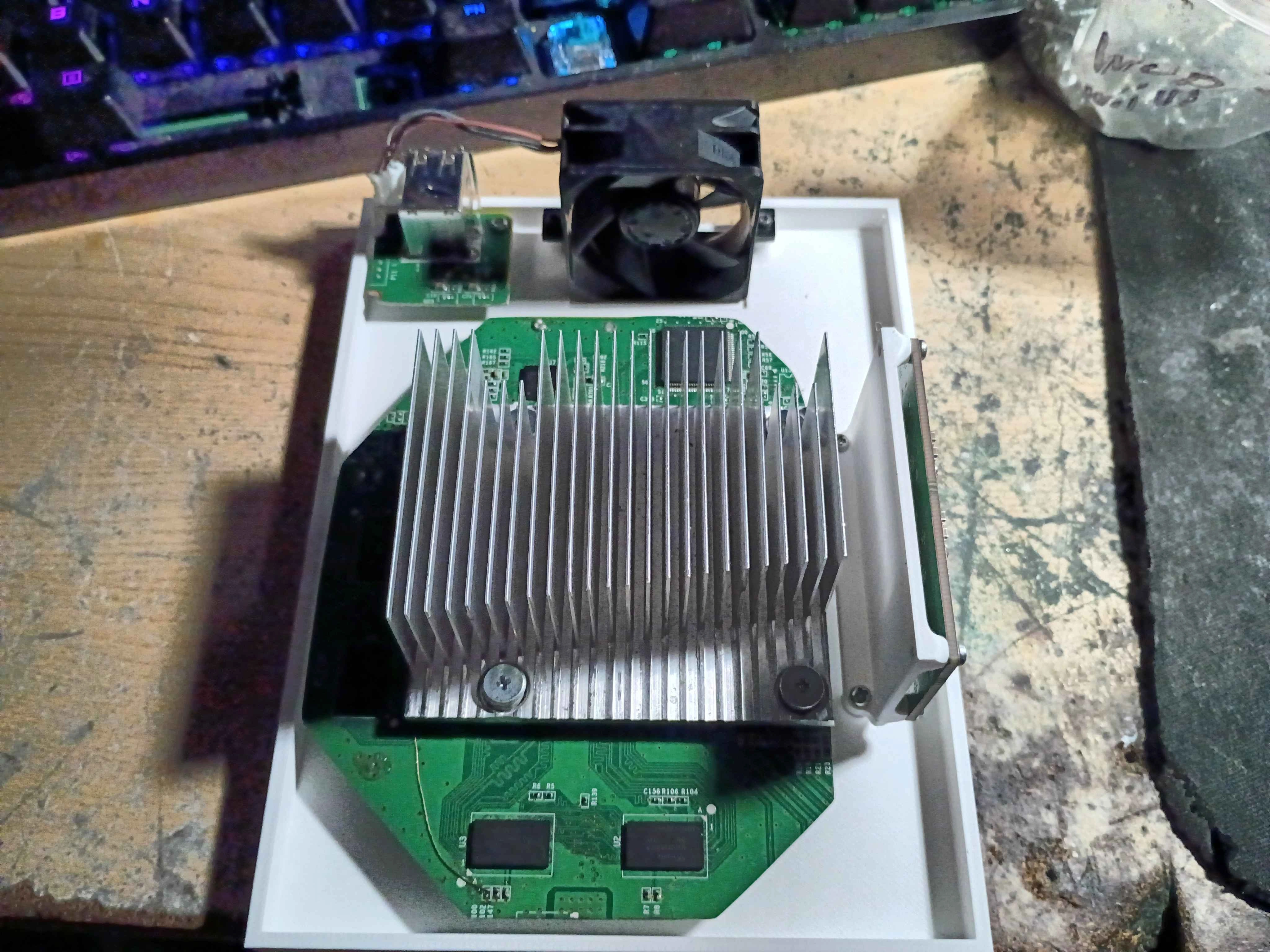
I am terrible at 3D CAD, so it took about 2ish days to get here. Getting a little better at least. Everything done so far has been done with OnShape. I don't think I'll ever have the brain power for a full on portable though.
The main goal is to have a use for the LOLWUN. I don't want to have documented everything about them go to waste..
It'll still work for LOLWUT's.....but why would you waste one on this?
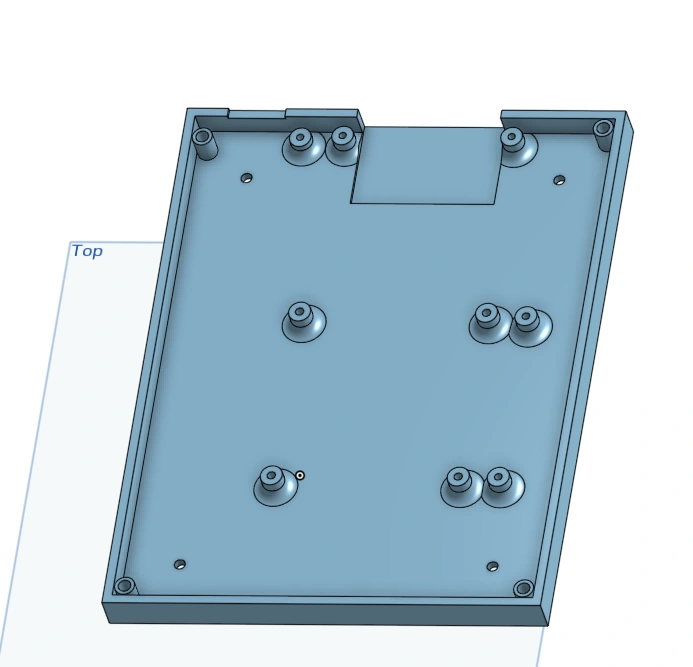
I think atp I'm done with the bottom half of the shell:
And working on the top half:
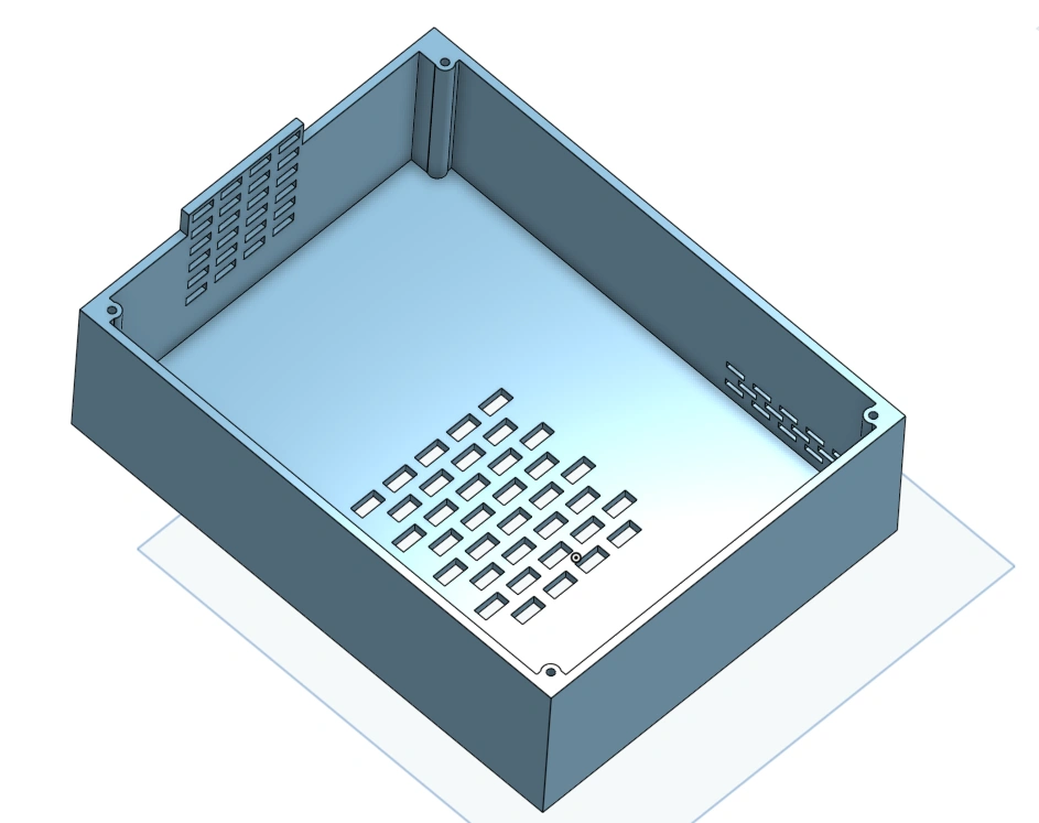
Right now it's just cooling holes (and that's not even done). I do want to have the power/eject buttons and all of the LEDs up there just so I have have my status indicators.
HDMI and power input will probably be mounted up there too.
I think the final shell with be printed in a pink PETG. Not that I want to, but i'm running out of filaments.
Finally, the hardware!
Last year I designed a power regulator board (4L) for this project and tried out AISLER's PCB service when tariff stuff was still constantly changing. They're OK if we look past the board copper going right to the very edge (JLC's and PCBWay's engineers usually scale it back about half a millimeter or something so the copper isn't exposed at the edge) and one of the 3 boards was X'd out and I wasn't notified. I remember the price being pretty alright though, so it's hard to complain.
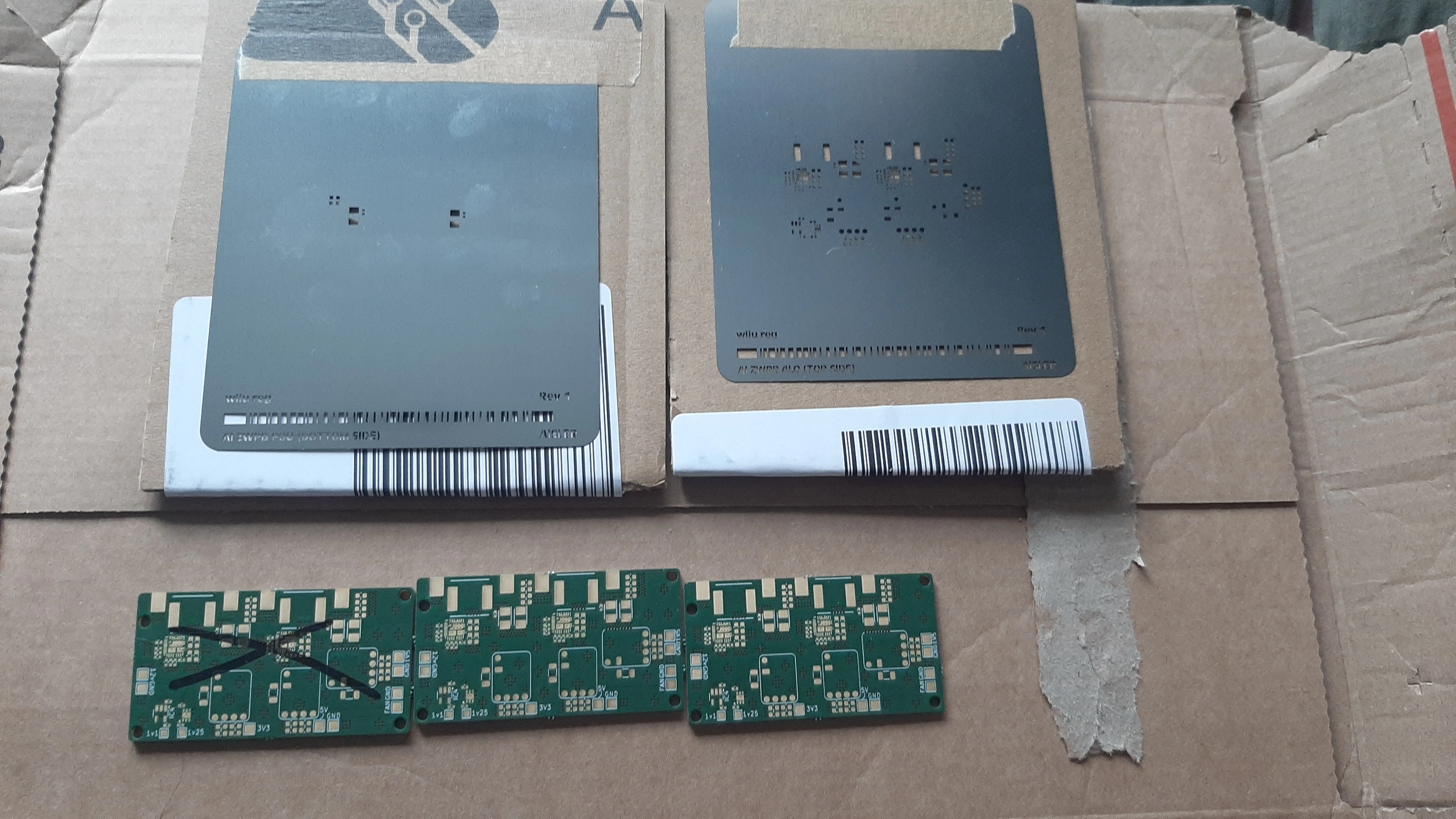
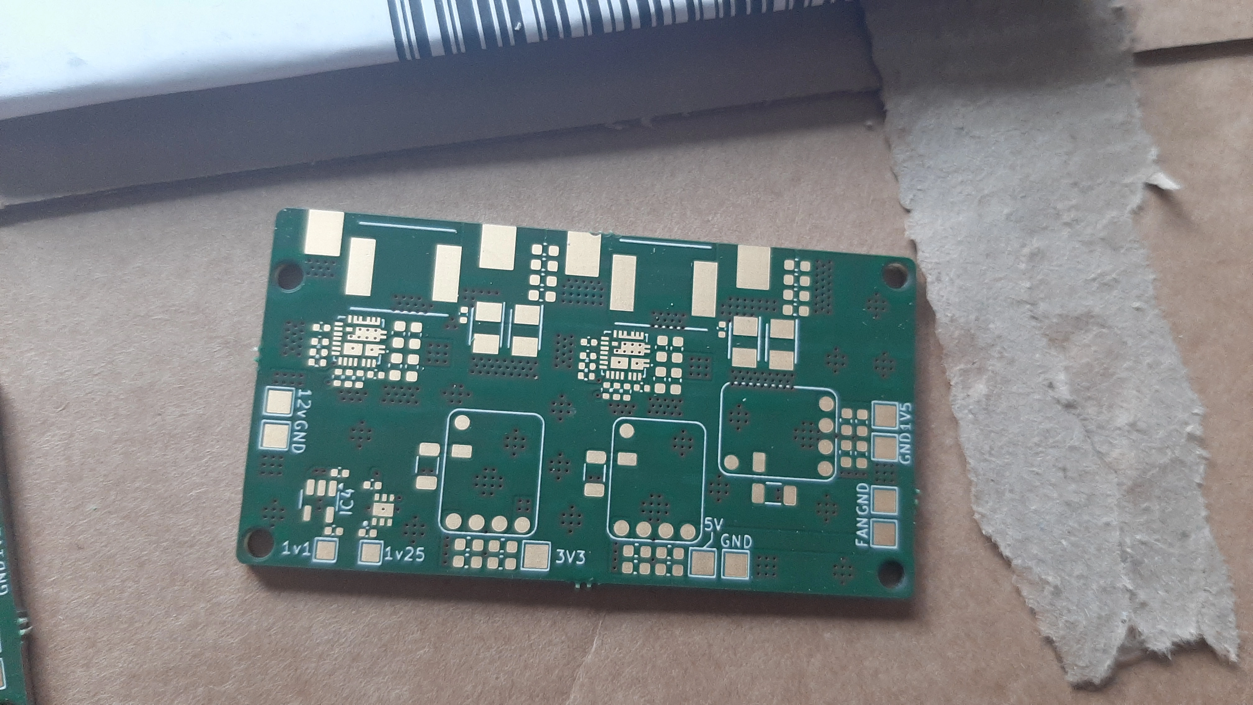
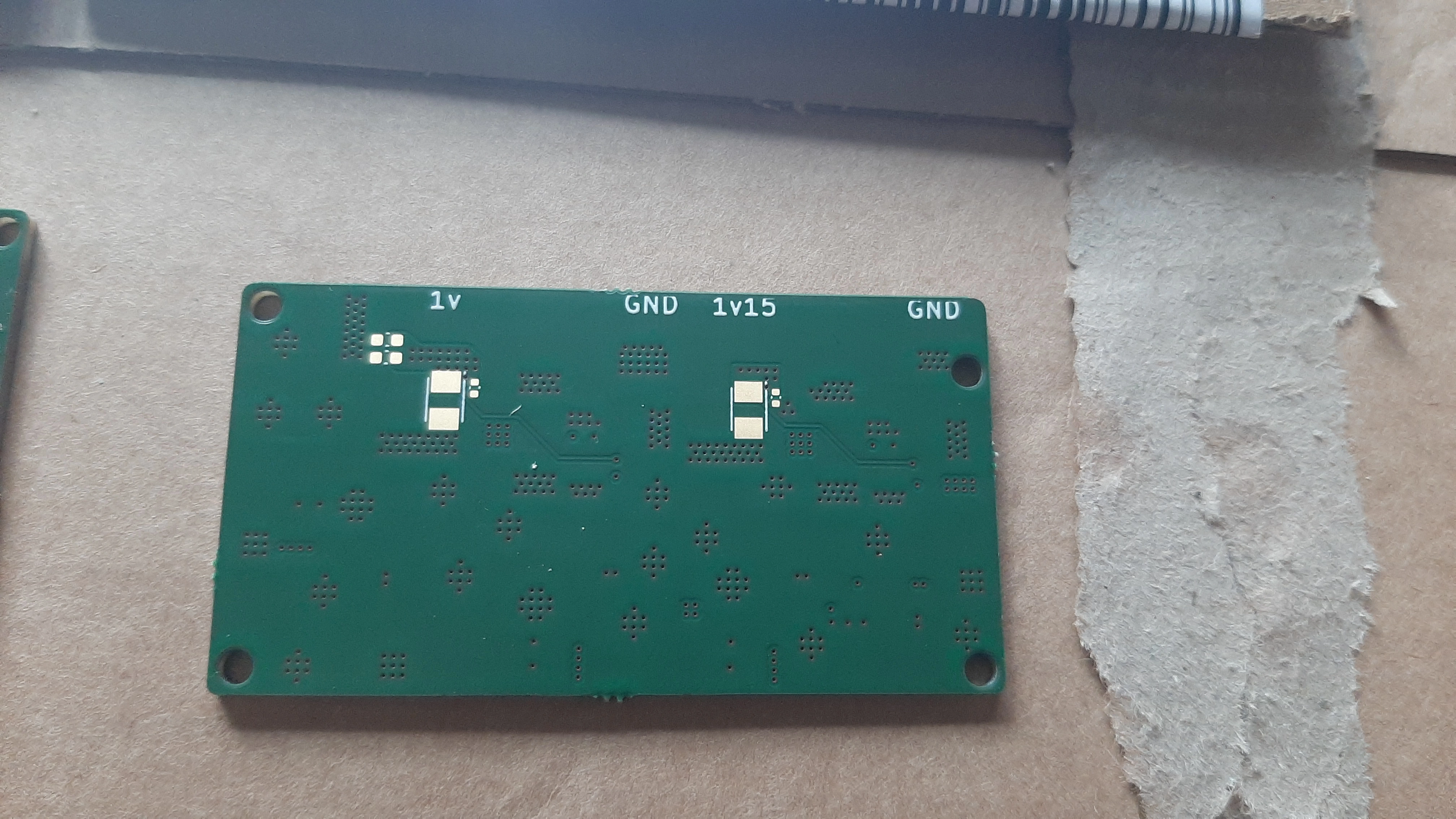
It's name? PiiSU. That will be the first and only time I will use that on this post for everyone's sanity.
The board is intended to take in 12v, but up to 17v at the very maximum should be fine.
Half the work was done for me, as I surface-mounted Yveltals reggies right to the PCB for 3v3, 5v, and 1v5. All of these are 1a or below, more than enough. Probably made the BOM a little cheaper too (don't quote me on this).
1v and 1v15 are using the SiC431's that are found on bistro and the failure that was minireg.
1v25 and 1v1 are using LDO's, powered from 3v3. It's not battery powered, it's fine.
Here's what an assembled one looks like:
(The bodge wire is not needed if you're using SiC431AED/SiC431BED. The C and D variants need an external 5v supply, which is what I had on hand after I fried one of them)
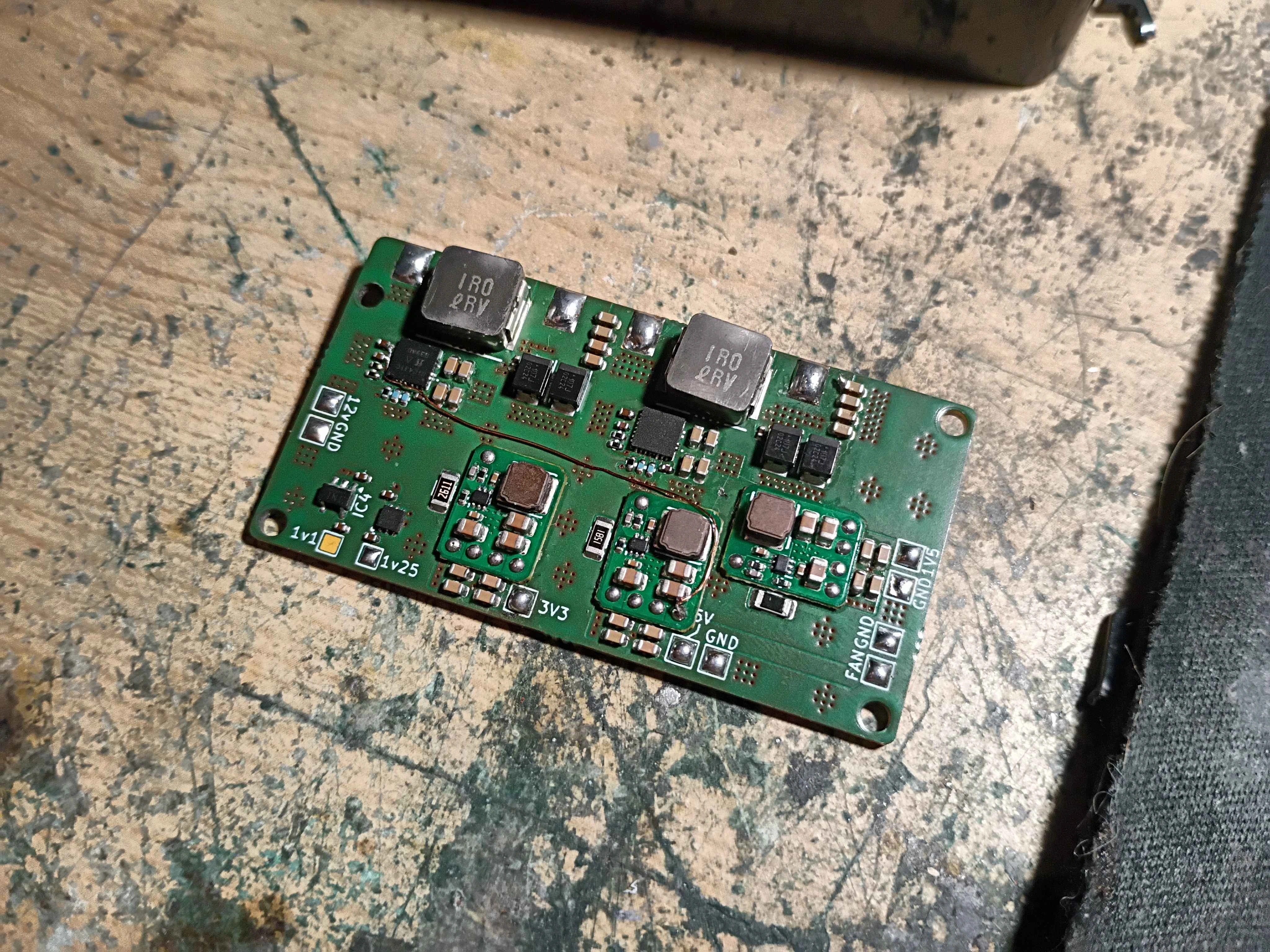
To mount the reg board on the inside, I designed this little mount:
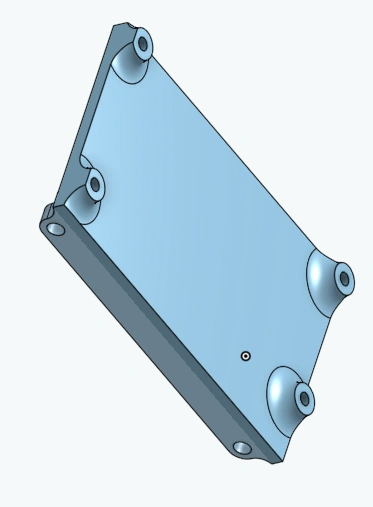
Secured to the mount/shell with those screws every Wii/Wii U has like 20 of.
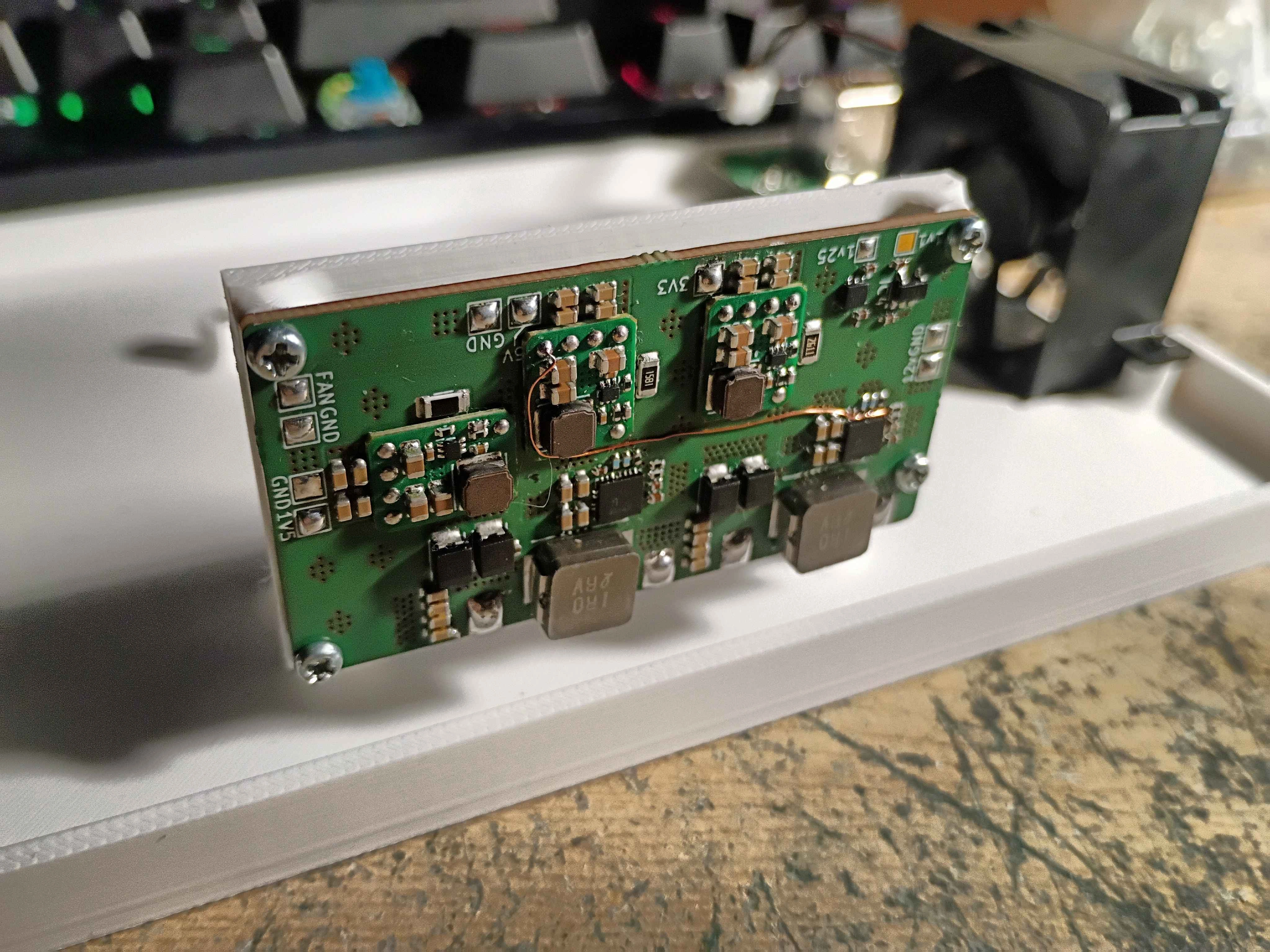
Inspiration from Crazy's PSU-Plus mount for Nold's Wii Micro!
This is the only custom PCB in this build, as I currently can't afford any others.
The heatsink I'll be using is the stock one. Unfortunately a 45x45x10 heatsink paired with the 50mm blower fan as shown in the R&D thread is just barely enough to cool an A5X before it shuts off from overheating. If it's like that for awhile, who knows what damage it could cause over time. I'm not really able to get a beefier heatsink, so this is the only option. The stock fan is used due to this. It's also why the power board is vertically mounted.
The USB ports at the back are also stock.
I want to have USB-C input to power it, but I don't have any trigger boards on hand, so I might go with the barrel-jack route or use the stock plug until I can get a PD trigger board.
When I do get around to it, I think the best solution is to request 15v and then have a buck converter take that down to 12v for the power board.
Option 2 is request 12v and I wire it straight to the power board, but that wouldn't ensure compatability with every PD block under the sun.
The entire current of the system is going to run through some switches that I bought for Wii Micros. Hopefully they'll be fine..
I'm taking out the AV and sensor bar ports. I just dont really want to have to deal with them, so HDMI only it is. Technically HDMI is harder to relocate than analog video but whatever. If a sensor bar is needed, there is the USB ports for 5v.
I'll decide if I want to bother relocating the WiFi module. With software patches its mostly gone, with the problem being vWii/Wii VC (the IOSes/HAI IOS are not patched, so the vWii or whatever Wii VC game wont boot if the module is missing).
Bluetooth and the 5GHz module will be kept for full Wii remote/pro controller and gamepad compatability. I think I'll use antennas from the Wii's WiFI module though, just because they're nice and flat.
For storage, I'm just going to keep the 32GB eMMC. All the games I would want to play can fit on it. The only worry is that its a Hynix eMMC that was failing but I just reformatted it and pretended that didn't happen (if I really get worried about the eMMC I'll reball a random one I find and put in that one) USB will be used for homebrew.
Funky things are happening!!
I am terrible at 3D CAD, so it took about 2ish days to get here. Getting a little better at least. Everything done so far has been done with OnShape. I don't think I'll ever have the brain power for a full on portable though.
The main goal is to have a use for the LOLWUN. I don't want to have documented everything about them go to waste..
It'll still work for LOLWUT's.....but why would you waste one on this?
I think atp I'm done with the bottom half of the shell:
And working on the top half:
Right now it's just cooling holes (and that's not even done). I do want to have the power/eject buttons and all of the LEDs up there just so I have have my status indicators.
HDMI and power input will probably be mounted up there too.
I think the final shell with be printed in a pink PETG. Not that I want to, but i'm running out of filaments.
Finally, the hardware!
Last year I designed a power regulator board (4L) for this project and tried out AISLER's PCB service when tariff stuff was still constantly changing. They're OK if we look past the board copper going right to the very edge (JLC's and PCBWay's engineers usually scale it back about half a millimeter or something so the copper isn't exposed at the edge) and one of the 3 boards was X'd out and I wasn't notified. I remember the price being pretty alright though, so it's hard to complain.
It's name? PiiSU. That will be the first and only time I will use that on this post for everyone's sanity.
The board is intended to take in 12v, but up to 17v at the very maximum should be fine.
Half the work was done for me, as I surface-mounted Yveltals reggies right to the PCB for 3v3, 5v, and 1v5. All of these are 1a or below, more than enough. Probably made the BOM a little cheaper too (don't quote me on this).
1v and 1v15 are using the SiC431's that are found on bistro and the failure that was minireg.
1v25 and 1v1 are using LDO's, powered from 3v3. It's not battery powered, it's fine.
Here's what an assembled one looks like:
(The bodge wire is not needed if you're using SiC431AED/SiC431BED. The C and D variants need an external 5v supply, which is what I had on hand after I fried one of them)
To mount the reg board on the inside, I designed this little mount:
Secured to the mount/shell with those screws every Wii/Wii U has like 20 of.
Inspiration from Crazy's PSU-Plus mount for Nold's Wii Micro!
This is the only custom PCB in this build, as I currently can't afford any others.
The heatsink I'll be using is the stock one. Unfortunately a 45x45x10 heatsink paired with the 50mm blower fan as shown in the R&D thread is just barely enough to cool an A5X before it shuts off from overheating. If it's like that for awhile, who knows what damage it could cause over time. I'm not really able to get a beefier heatsink, so this is the only option. The stock fan is used due to this. It's also why the power board is vertically mounted.
The USB ports at the back are also stock.
I want to have USB-C input to power it, but I don't have any trigger boards on hand, so I might go with the barrel-jack route or use the stock plug until I can get a PD trigger board.
When I do get around to it, I think the best solution is to request 15v and then have a buck converter take that down to 12v for the power board.
Option 2 is request 12v and I wire it straight to the power board, but that wouldn't ensure compatability with every PD block under the sun.
The entire current of the system is going to run through some switches that I bought for Wii Micros. Hopefully they'll be fine..
I'm taking out the AV and sensor bar ports. I just dont really want to have to deal with them, so HDMI only it is. Technically HDMI is harder to relocate than analog video but whatever. If a sensor bar is needed, there is the USB ports for 5v.
I'll decide if I want to bother relocating the WiFi module. With software patches its mostly gone, with the problem being vWii/Wii VC (the IOSes/HAI IOS are not patched, so the vWii or whatever Wii VC game wont boot if the module is missing).
Bluetooth and the 5GHz module will be kept for full Wii remote/pro controller and gamepad compatability. I think I'll use antennas from the Wii's WiFI module though, just because they're nice and flat.
For storage, I'm just going to keep the 32GB eMMC. All the games I would want to play can fit on it. The only worry is that its a Hynix eMMC that was failing but I just reformatted it and pretended that didn't happen (if I really get worried about the eMMC I'll reball a random one I find and put in that one) USB will be used for homebrew.


 . This was also the point where I ran out of 32AWG wire, so everything was done with 38AWG.


