Resistor value

Joined
Nov 9, 2017
Messages
874
Likes
834
Location
CA
Portables
8
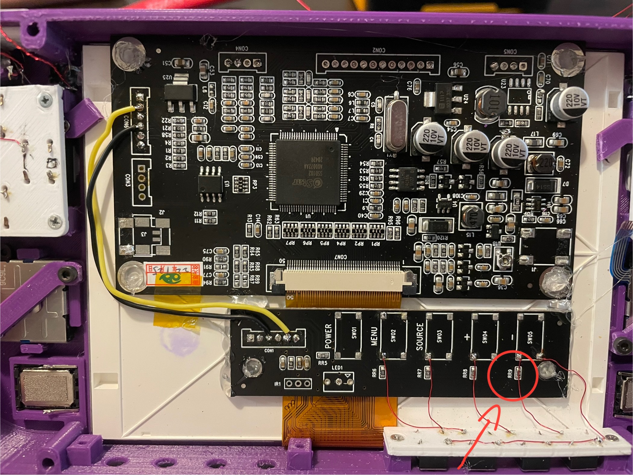
Does anyone know the value of this resistor RR9 for the black board ZJ050NA-08C. Any help is appreciated thanks in advance.
IMG_2139.jpeg
 
sorry to necro a bit, but i lost the control board. does anyone have a list of all the resistor values for each button?
 
Power: R5 - 10K Ω
Menu: R6 - 22.1K Ω
Source: R7 - 6.82K Ω
+: R8 - 20k Ω
-: R9 - 680 Ω

Let me know if these work. There's no reason they shouldn't but It'd help to verify I took my readings correctly.
 
Power: R5 - 10K Ω
Menu: R6 - 22.1K Ω
Source: R7 - 6.82K Ω
+: R8 - 20k Ω
-: R9 - 680 Ω

Let me know if these work. There's no reason they shouldn't but It'd help to verify I took my readings correctly.
Hey Cy! long time no see. Thanks for the values but it looks like those match closer to the newer KYV N2 V6 (which I also have because I tool those measurements. I managed to find the values of mine through some old pics.

For this version they should be:

- : 510
+ : 1.2k
Source: 2.4k
Menu: 5.8k

For some reason though I can’t get it to work. Screen turns on and says NO SYNC and shuts off. I tried pressing each button during this period and they do nothing.

Before when I had this working I wired each switch individually to KEY on the driver board. This time I took a different approach more like the traces on the button board. For some reason there is a resistance of 2.9K at KEY pad when no buttons are held and I’m not sure if that’s normal. I measured it while wires desoldered and KEY pad is always 2.9k I guess?

I checked the resistances of the actual key wire for each resistor to the end of the wire and it checks out. 0 R on all resistors from soldered wire side to KEY and correct resistance values from the other side of the resistor (switch leg side) to the end of KEY wire. This makes me fairly certain that this approach would work, but correct me if I’m wrong.

Based off this information am I doing anything wrong? I would appreciate some assistance to be able to get passed no sync shutoff.

Edit: it looks like everything I did was right! It was just VGA mode :facepalm: and mixed up which buttons were which. The new values to button for this older board are as follows:

Menu : 510
Source : 1.2k
-: 2.4k
+: 5.8k

I started just hitting the buttons and eventually figured it all out. Bit of an obstacle picking up such an old project haha
 

Attachments

  • IMG_5844.webp
    IMG_5844.webp
    244.8 KB · Views: 1
  • IMG_5843.webp
    IMG_5843.webp
    398.8 KB · Views: 1
Last edited:
Hey Cy! long time no see. Thanks for the values but it looks like those match closer to the newer KYV N2 V6 (which I also have because I tool those measurements. I managed to find the values of mine through some old pics.
Please forgive me for not recognizing you. Are you able to refresh my memory on who you are and how we've interacted before? It can be in DMs or over Discord or whatever.

When you asked this question:
sorry to necro a bit, but i lost the control board. does anyone have a list of all the resistor values for each button?
I was under the impression you were looking for the resistor values on the screen control board there. The screen driver board appears the same from what I can tell by the pictures you just provided, but it's honestly a bit difficult to see. Do you not have the original driver board with you? I'm not saying that you're wrong, it just looks the same to me as the other driver boards, and thus I would expect the resistance values to be the same. Have you tried what I provided? I'm just curious, sorry if anything in this post came off as rude at all. Just trying to help clear things up! :)
 
Please forgive me for not recognizing you. Are you able to refresh my memory on who you are and how we've interacted before? It can be in DMs or over Discord or whatever.

When you asked this question:

I was under the impression you were looking for the resistor values on the screen control board there. The screen driver board appears the same from what I can tell by the pictures you just provided, but it's honestly a bit difficult to see. Do you not have the original driver board with you? I'm not saying that you're wrong, it just looks the same to me as the other driver boards, and thus I would expect the resistance values to be the same. Have you tried what I provided? I'm just curious, sorry if anything in this post came off as rude at all. Just trying to help clear things up! :)

I don’t blame you! We talked on discord a good amount in 2020? It was when you were building your first Gwii.

Correct, I was looking for the control button board resistor values. All of the buttons seem to work, I believe its just different from the other (newer) KYV N2 V6 I have. I found some old pics and managed to get resistor values based off code and it works.

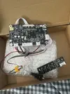
The resistor values for the newer KYV N2 V6 (in pic) are as follows (from resistor codes):

- : 680
+ : 2k
SRC: 6.8k
Menu: 22k

Hopefully this thread will help others looking for resistor values.
 

Attachments

  • IMG_5848.webp
    IMG_5848.webp
    759.8 KB · Views: 1
  • Like
Reactions: cy
Back
Top