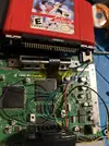
The first thing that jumps out at me here is the gauge of wire you're using is way too big for smaller solder connections. Looking at the RCP pin here:
This part of the picture is blurry, but I don't think anyone could've possibly made this connection with this wire gauge without shorting one of the nearby pins.
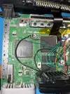
It's also very hard to follow which wire is going where when I look at this:
Again, this comes back to the gauge of wire you're using. I would use something like
this 34 AWG magnet wire I found on Amazon. It's what most people in the community use.
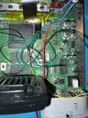
Also, that the solder joint on your 5v line looks terrible:
Although, I'm curious, why do you have a wire going to the 5v rail in this stage of testing? You aren't at a point where you should be testing with a power management system and batteries yet, and I'm not so sure the console would even work in it's current state due to other voltage regulators on the board if you were using a PMS to power it instead of the console's original power brick.
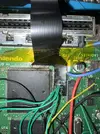
Finally, while these flexes are flexible (hence their name), they are really sensitive to being flexed over and over again. I had a flex quit on me after barely doing anything simply because I had flexed it a little too much the wrong way. Also, I see two wires under the flex there, that's definitely not ideal. I don't think there's any reason you can't relocate those wires (or the whole capacitor itself) to the back of the board instead of going under the flex and creating even more potential for flex issues:
Any one of the reasons I listed above could be why this isn't working. Honestly dude, I feel like you should come back to this once you have more experience. It's easy to make very expensive mistakes when you lack the proper knowledge and skillset. It often leads to people wasting money, getting frustrated, and quitting altogether. Not what anyone want to see...
Wishing you the best of luck regardless.