Release Ps2 voltage regulator board

Joined
Nov 9, 2017
Messages
868
Likes
823
Location
CA
Portables
8
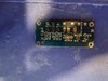
thanks to my good friend @Mister M for designing this regulator board for the advance ps2 trim. It’s been about 2 weeks since I put my board together and tested it, I’m now ready to share the files and bom with everyone who may want to use them.

Here are the Digi-Key parts list. Everything seems to be in stock at the moment.

https://www.digikey.com/short/130nv3d8


Regulator board download

R6 - is 953k ohm resistor. In the download bom it says 95.3k


3452787A-762E-4492-B27E-237EC153FA90.jpeg
F7E8556D-0DD0-4775-8DF1-F0B8E54F0B5B.jpeg
D165BADC-809B-4C00-845C-3FE333A63E02.jpeg
7B17AE8E-97CC-451A-998C-7CD7652F7009.jpeg
08B492A4-E490-4305-AC65-8B3592C1DC54.jpeg
 
Last edited:
I tested it with a usb c 3amp power bank, it worked but my power bank kept turning off. I’m currently testing another power bank module.
 
I did an update to the BOM, so everything can be sourced off LCSC with no out of stock Parts. Maybe this is useful for someone. The fixed Resistor value and it's lcsc part is updated. The only downside is that some Parts aren't from the same manufacturer anymore, but the tolerances are the same. Prices are updated for today and the parts will end up to cost around $15-$20
The BOM can be placed directly in the lcsc BOM tool, the Quantity is suitable for one Board.
Be aware that some parts have a minimum quantity to order.
 

Attachments

Hey, I have a Question about the Board. As I just saw a Video about how Inductors work, I am now a little concerned about something called "flyback". On disconnection of the power source it can lead to very high voltage spikes. I do hope this isn't a problem in this particular design as I don't see any diode.

I don't know about sharing links here, I will look up the rules Tomorrow and share the yt link if possible.
It hasn't been a problem for any regulator board designed so far, but if you're concerned about flyback you can integrate a clamp diode to prevent it
 
Alright, thank you for the reply, I guess since you answered this, I will not unnecessarily share the Video here.
 
Ok I built one of these and the voltages are correct for the 2.5v and 1.25v rails, but the other 3 are all wrong. The readings I get are as follows:

5v pad - 0.06v
3.5v pad - 1.2, then drops to 0.82ish
1.25v pad - 0.78

The linear regs are all correct.

Any idea what I've done wrong?
 
Ok I built one of these and the voltages are correct for the 2.5v and 1.25v rails, but the other 3 are all wrong. The readings I get are as follows:

5v pad - 0.06v
3.5v pad - 1.2, then drops to 0.82ish
1.25v pad - 0.78

The linear regs are all correct.

Any idea what I've done wrong?
Check for shorts on TLV62130RGTR. Can you upload some pictures
 
Yea that might be the problem mine weren’t like that when I ordered them. Do you have another board that they’re not shorted ?
 
Yea that might be the problem mine weren’t like that when I ordered them. Do you have another board that they’re not shorted ?
Unfortunately they all look identical. Awell, I'll call this one soldering practice and order some others.
 
Back
Top