(Disclaimer) I feel like the odds of you having a "no video" issue exactly like mine is unlikely, but I've been meaning to post my findings from my N64 repair on here since I think I'm the one of the first people online (or the first person online) to have seen a failure with this specific resistor array on an N64. With my cursory Google searches, I found some examples of people replacing the Jumper Pak resistor arrays, but no examples of people replacing the 75Ω video termination resistor array. (End of Disclaimer)
No, I never found a replacement chip. I fixed the issue without replacing the chip or recapping anything. In my case, it was a failure of an SMD resistor array, which was a first for me. I even kept the failed part as a trophy. The middle two 75Ω resistors in RA1 were open circuit (the refdes on yours might be different if you have a different version PCB than mine). I would check the resistance of each resistor in this pack on your N64. I was able to find this by measuring resistance in-circuit** with my digital multimeter. It's pretty obvious if it's an open circuit or 75Ω. You'll see something around 70-80Ω if it's good, and something waaay over 100kΩ if it's bad.
Good luck with the console. If you have an oscilloscope, take screenshots of the chroma/luma/composite outputs. In hindsight, it's clear that the signal was missing the 75Ω termination resistor because it looked like a 5V DC signal with "noise" (aka a very faint composite video signal) imposed on it.
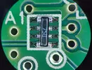
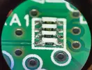
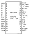
I've attached photos of my repair. The resistor array responsible for my video issues has "750" marked on it, indicating it is a 75Ω resistor array. I've also attached a pic of the pinout of MAV-NUS that I found from Google. Pin 29 "Y (LUM)", Pin 27 "Video", and Pin 25 "C (CRM)" should all have 75Ω to ground from this resistor array.
**I know a lot of people say measuring resistances in-circuit is bad and should never be done. In this case, it was fine.