- Joined
- Aug 13, 2019
- Messages
- 27
- Likes
- 4
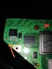
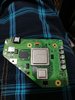
hi , as in one of tutorials (basic trimming guide) we can remove LDO for better life of battery but we should remove LDO if we are doing G-boy kit , but in the tutorial of assembling G-boy there is no evidence of LDO being removed and also i couldn't find any documentation on which pad should i feed in from my custom regulated 1.8 v ( i guess to heatsink ),and oh yeah another thing i messed up C3 smd capacitor i don't know the value to replace it is it important?