Question How should I organize the sd card that I’m using with my pms pd 3.1

Joined
Aug 9, 2024
Messages
9
Likes
2
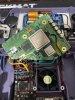
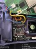
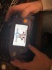
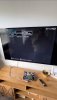
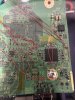
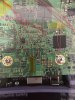
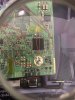
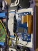
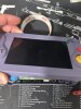
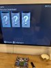
I’ve been trying to build an ashida, and I can get my trims to boot just fine. But after wiring everything together It works great for a few glories minutes, and then I get a black screen. I’m wondering if my sd card doesn’t have the appropriate files on it or something and I’ve just bricked several trims. Is that a possibility? Would anyone be willing to show me how their software is set up on their sd card when using a pms-pd-3? I also had to add several of the .wad files in order to get RVLoader to install initially, do I still need those on the root of my sd card when the ashida is all buttoned up? Sorry for the long winded question, I’m pretty new at this! The community has been awesome so far though, so thank you!
 
If the console boots to RVLoader and then fails afterwards, your file structure probably isn't the issue.

Can you provide photos of these bricked trims, your wiring, and which microSD card you're using? May as well include your current file structure just to eliminate that as a factor.
 
Yeah! Sorry i probably should have led with some photos. Thanks for getting back to me. I’ve tried to include some videos too so hopefully yall can see what’s going on. I actually did get the vga screen to boot briefly but then as soon as I closed up the case the ips screen just stays black. Doesn’t even illuminate blue with the vga text anymore. I re-soldered all my data lines and made everything as short as I could. Composite output shows up on my TV but now I can’t get anything to show up on my ips screen. I even swapped H and V sync lines a few times because I saw a few threads here where that worked for someone. Anybody have any ideas of what could be going on?
 

Attachments

  • IMG_8051.jpeg
    IMG_8051.jpeg
    1.6 MB · Views: 110
  • IMG_8046.jpeg
    IMG_8046.jpeg
    2.2 MB · Views: 114
  • IMG_8047.jpeg
    IMG_8047.jpeg
    2 MB · Views: 123
  • IMG_8048.jpeg
    IMG_8048.jpeg
    1.9 MB · Views: 113
  • IMG_8049.jpeg
    IMG_8049.jpeg
    2.1 MB · Views: 120
  • IMG_8050.jpeg
    IMG_8050.jpeg
    1.9 MB · Views: 97
  • IMG_7974.jpeg
    IMG_7974.jpeg
    1.4 MB · Views: 120
  • IMG_8052.jpeg
    IMG_8052.jpeg
    1.6 MB · Views: 108
Quite often when something stops working after closing the case it's because strain/pressure has been applied to a moving wire or dodgy joint, occasionally even causing a short.

Your U10 wire concerns me, it appears there's enough exposed wire to short against a neighbouring via when pressure is applied. I'm also not too happy with the H/V sync wire you've chosen. That magnet wire is quite thick and springy, I worry that they might move and short against each other when the case is closed.
Same with the i2s/i2c wiring. It's hard to tell precisely from the photos, but I'd call that a shorting risk too. Ideally you'd have all of the wires pointing in the same direction with little to no kink bends and only as much exposed enamel as absolutely necessary.

I'd inspect all of your wires under a torch one by one and see if any of them move when you apply pressure or rotate the top shell around to close the case up. From what you've described that is your most likely source of failure atm.
 
Thanks! I just finished up cutting off the excess tinned portions of my wire and re-soldered everything again now all facing the same way, so hopefully there are no potential shorts. I checked a few times opening and closing the case to make sure everything stayed put, and everything looks rock solid. I reflowed the H and V sync lines and just put some tape down to make sure my magnet wire doesn’t move around at all. I tested the continuity between the pins and pads and they are making good connection with the driver board and they are not shorted together at all. What type of wire would you suggest using instead if that might still be a problem? After wiring everything up, I tried powering it on without closing things up all the way, and i was still met with a black screen. I then wired it back up to composite to test on my tv, and It works great on my tv! I am surprised at how reliable it is booting up. Any ideas on what I’m doing wrong when it comes to wiring up the driver board and ips screen? Could it be that I killed the driver board somehow and now it’s toast? I know that my mode line is getting 3.3v because the composite won’t work when it’s still connected. I also know that the driver board is receiving 3.3v. Any help would be greatly appreciated, I’ve been scratching my head over this one for a while.
 

Attachments

  • IMG_8062.jpeg
    IMG_8062.jpeg
    1.9 MB · Views: 119
  • IMG_8063.jpeg
    IMG_8063.jpeg
    2 MB · Views: 105
  • IMG_8064.jpeg
    IMG_8064.jpeg
    1.7 MB · Views: 116
  • IMG_8067.jpeg
    IMG_8067.jpeg
    2.1 MB · Views: 103
  • IMG_8065.jpeg
    IMG_8065.jpeg
    1.6 MB · Views: 111
  • IMG_8066.jpeg
    IMG_8066.jpeg
    1.5 MB · Views: 111
U10 wire still looks suspect to me with that long exposed tin, but aside from that, a much better arrangement! You were right to use magnet wire, we just recommend using a thinner gauge like 34 or 38 AWG. The thinner and softer wire is easier to tin, twist, route, and doesn't spring or rip solder joints.

As for the screen being the problem, that's definitely a possibility. If you get proper display on your TV from composite, then that narrows things down a bit.

My first port of call would be to re-install the VGA patch just in case it's an intermittent software issue. Failing that, have you verified whether feeding composite to the Ashida screen provides a picture? If it doesn't work (and you have checked that you haven't accidentally soldered a one of the VGA GND wires to a signal pad), then the driver board or LCD panel are likely at fault.
 
*update -got the new Rvl-DD drive board and now the display is working great! Relocated Bluetooth and MX chip and both are working very reliably. Only issue now is that the pms-pd-2 is only detected about 25% of the time, and the audio hud flickers on and off the screen with the volume percentage at crazy values. Audio is having some issues as well. I’m thinking it’s gotta be my i2c/i2s lines. Going to use shielded wire for those and see if that resolves the issues. Can I twist the I2c/i2s lines together to try and combat interference or is it better to use shielded wire to ground?
 
Back
Top