Heya! Update four here we go! (Spoiler the PICO boards arrived! ^^ )
Quite a bit has happened since last time! First off after some back and forth I decided to make a version where the tracks were straight and not length matched. Primary reason being that skew would not be large enough to matter anyways, and it would let me spread some of the traces further apart to limit cross coupling.
However, being stubborn and not wanting to admit all the time I spent length matching was a waste, decided to just make a panel with both the length matched traces, and the straight traces, so that I could test both XP
I’ll include a detour into impedance matching, that turned out to be irrelevant, and can be skipped if you don’t care XP
I found the calculations for the impedance for the ram, which was set to 45 Ohm +-10%. While the PPC750 which the CPU is based on also mentions an impedance of ~45 Ohm. So, I went back to the calculator in KiCad, and double checked that with a 1oz copper weight, we would get 65 Ohm impedance on the traces, while a 2oz copper weight would drop the impedance to 55 Ohm.
Stock ZQ on the Wii is 270 Ohm, so the impedance is 270/6=45 Ohm. ZQ should be between 210 and 270, which is an output impedance of 30-50 Ohm (using +-10% for the extremes). Changing the ZQ higher could increase the impedance, but it would go outside what the ram is built for.
Meanwhile the Power PC 740-750 also mentions 43 Ohm without any option to change it the way the RAM ZQ can be changed.
Rob’s recreation used 1oz and the same trace width, so he had it running with 65 Ohm impedance traces. However I got paranoid that since my design is so compact and deviates from the stock design so much, I though that maybe trying to go for a lower impedance might improve my chances, or at least not hurt them. Not that the lower impedance would change the cross coupling, but that if I had multiple noise factors, then removing the noise from signal reflection from bad impedance matching could improve the overall signal integrity. And it didn’t cost that much extra for the upgrade, so it seemed worth it.
However, I had forgotten a tiny little detail… Changing the copper weight changes the minimums… Instead of having a trace spacing of 0.1mm, I now needed a spacing of 0.15mm… Which would be completely impossible… That amount of spacing would mean you can’t snake traces out from the CPU pins. Maybe you can use lower minimums in BGA fanout, but I wanted to order the boards quickly, so I decided to drop it.
So, I felt ready to order, I had triple checked everything. Made both a length matched version and a straight version (during pride I know XP ), and made my own panel. I checked the design against the DFM tool for JLC, the uploaded the design and toggled all the important settings:
- 6 layer board
- 0.8mm board thickness
- 2oz copper
- The smallest vias JLC allows 0.15mm
- Castellated edges
- Color Purple!
And saw with dread how every option increased the price... But I decided to bite the bullet anyway!
JLC says their review should take between 10min to an hour… An hour came and went… Then two… I checked when they were supposed to be open, and they are supposedly running 24h during weekdays. So, I keep waiting, trying to busy myself with other things... It’s a complex circuit, it’s no wonder it is taking extra time… At the five and a half hours mark it finally went through, whoop! They up charged me more for the panel but otherwise seemed like I was in the clear, double whoop! So, I paid and went to sleep in the knowledge that everything would be fine.
Foreshadowing is a literary device...
Anyway... The next morning, I saw I had an email from their techs... telling me that with the 2oz copper I had ordered, I no longer met their minimums. This was apparently not caught in their initial review… I talked it out a bit on the discord before deciding to print a test print on 1oz instead and remove all the expensive options I could to bring the cost down.
So, I got rid of the panel, only ordering the straight ( :/ ) trace version, in 1oz copper, in boring green, and without castellated edges. It got the cost way down, and would make it easier to do a reprint in case I'm not a goddess of perfection XP , and there were any issues which slipped by.
Then in intensely waited for a week till the boards arrived on Thursday XP
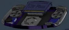
They are kinda scary small the PICO is! And it turned out quite well even if it isn't purple ^^ Though I missed out on putting “2026 Nintendo AGB-RVL-01” on the bottom silk screen. But maybe for a second print if I needed it.
This weekend I started soldering, focusing on the back. However, I discovered that I had ordered the wrong feedthrough caps, ordering 100pF instead if 1uF. I have no clue how I picked the wrong size that badly... So got to make another order and get the right ones this time. Good thing I almost never make mistakes XP
I had planned to be stubborn and just use the regular Hollywood 1 from the regular wii I just got for this. However I was convinced on the discord to not be stupid and to just order a Mini so I can get better thermals and better undervolting. Thanks everyone ^^ And thanks to flux_sniffer for helping me on how to source the correct mini version ^^
As for the actual reballing process… Lining up the balls is fine, but getting them to melt into place without moving using hot air is kinda a pain. So I decided to cheat XP I decided to try and build an IR top heater so that I could melt the balls into place without hot air. I found a guide, the components, some aluminum extrusions to make a thing to hold it, ordered everything, and felt quite clever about myself finding a way to avoid doing something really difficult XP And I do a lot of smd soldering so it felt like an investment regardless, just putting my boards under the IR top heater to melt everything all at once as if I were baking the board.
However… The IR top heater never arrived… Ali Express says it did, but it ain’t here :/
So, I guess I have to keep practicing with hot air till I get the skill down...
Along with the main PICO board, I also ordered some cheaper 2 layer boards, including a simple test dock which fits the AVE, and some regulators, and other simple features. It’s there to power the PICO and to get the graphics data out, so that I can test if the boards works when I finish soldering it.
I plan to make a nicer TV dock, and the GBA handheld dock later, however I first need to test if the PICO even works to begin with.
Now while aggressively waiting for the PICO PCB to be manufactured, and now while casually waiting on the HW2 to arrive, I’ve been working on some 3D modelling, CAD’ding out the GBA as much as I could, starting with recreating all the buttons, down to the rubber domes XP Using the Wesk scans for reference, and calipers on the parts I have at home.
I also modelled the full shell in in fusion, trying to keep it as accurate to the stock GBA as I could. Even managing all the painful curves on the backside using lofs. (Apparently there's an option to change how the loft's connect, letting you use tangents or curvature, which helped with the smoothness)
I had planned to print it today so that I could include it in the update, but half of the print came loose early on and turned everything into a mess… And I didn't realize in time to start another print today :/
However, with 3D models in place, I also started looking at the internal layout and how to cool everything! Even though the Wii uses very little power, having no cooling while being this small feels like a bad idea XP
Though, with the Wii being in the cartridge, and the cart being removable, we meet the problem of how to attach a heat sink to it while it is inserted?
My current plan that I like is this:
Put the heat sink on a cammed track.
While the cart is not inserted the heat sink will be in the down position, held in place by a spring.
As the cart is pushed in, it will push against an arm on the heat sink, pushing the heat sink forwards with the cartridge.
As the heat sink moves forward, the cammed track pushes the heat sink upward into the cartridge, with a bit of force to allow for good contact.
A thermal pad on the heat sink, will act as the thermal interface material, and a soft buffer.
Removing the cartridge will do the same in reverse, the cart and the heat sink travels together outwards till the cam track pulls the heat sink down and free from the cartridge. Then a spring pushes it the rest of the way to the down position.
Are there better ways of doing this? Yes probably. I could get rid of the interlinked system and use an external button to do the same. I could also use springs more to give contact pressure. I could use graphite for thermal interface instead of thermal pads. But this is my plan for now, I want to make some tests based on this to see how well, or how badly this will work before I abandon it.
---
And I think I will leave it here for now XP
I need to wait on the Wii Mini with the HW2...
Practice hot air reballing more. :/
Finish up soldering the top of the PICO and solder the test dock. ^^
Then actually test if the wii will boot XP
I got the boot debug pads exposed so if there is any life in it I will be able to get something, hopefully XP
Anyway that's enough for this update. Maybe I'll have something booting in the next one, or I'll be deep into debugging and learning from potential mistakes XP