Worklog Kolenot's Ashida Worklog

Joined
Nov 3, 2025
Messages
118
Likes
67
I guess it's time that I finally started this since I'm getting to the point where I'd like someone to double check.
But lemme first give you all the info.

What am I doing exactly?

  • I'm (obviously) making an Ashida. But I'm trying to make it as decked out as possible.
    1. Wifi module
    2. Bluetooth Module
    3. MX chip
    4. RVL-DD
    5. U-Amp-2
  • I'm also gonna make a custom theme for RVLoader
    The theme isn't gonna be something fancy, but rather more flexible.
    I'll make a worklog of that later on in a different thread.
Meet the Team
Wiimote for scale since I don't have a banana or a Chinese NES
RIIP
Viictim2
Labrat
20251129_150821.webp
20251129_150905.webp
20251129_150921.webp
Died in a tragically by a maniac who didn't know how to properly knew how to expose the copper of the via'sHopefully he learned his lesson bc this one is currently on the chopping board.This wii is destined to only be a digital dummy cuz he's so fat he needs double the food of other wii's and has 2 extra fat layers.
Currently a testing dummyCurrently alive with recently the Bluetooth wires connected
1766196906308.webp
This rat decided he's become a snail and lives now in the shells of the previous victims. (still fat though)
20251130_024150.webp

Where am I?
In front of my desk writing this thread. (ok now a bit more serious)
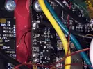
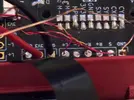
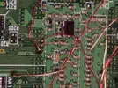
  • I've relocated the U10 since I saw that the simulation isn't a perfect replacement
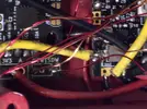
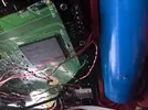
  • Prepared the Wifi module with cables (not connected to the wii yet, 2x 3.3v and Gnd are 30AWG, rest is 34AWG)
    1766197310407.webp
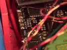
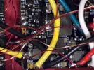
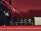
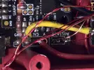
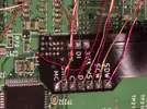
  • Connected the 2 Bluetooth signal cables to the wii
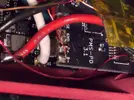
  • Trimmed second Wii (tested too)
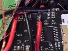
  • Trimmed MX chip
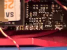
  • Exposed via's for the RVL-DD flex cable
    20251214_174645.webp

  • I've prepared a plan to connect all the components (didn't add the wifi and the MX chip since I'll be following the OMGWTF trimming guide and use 30 AWG for GND and 3.3V and 34AWG for the signal/data cables)
1766447796891.webp

What do I need help with right now?
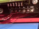
  1. Is T+ needed?
  2. What is the purpose for the A port of the interface board (the board where you put the U-amp)
  3. Is it OK to have the wires for the Bluetooth module a bit longer so the follow the same direction as the other cables?
  4. Is my Plan fine?
    • Do I use the correct wire thickness
    • Am I missing some wires
    • Are there more wires that need to be shielded (more then mentioned)
    • Is there anything else that might be wrong?
  5. Why did Nintendo hate the Bluetooth Module so much that they didn't gave it extra via's?
  6. Did I make some typo's that I'll have to fix once you post them?
  7. Any ideas for things to print to mount the chips (wifi, Bluetooth, MX)? (I've found a couple, but options are always welcome)

Looking forward to your support.
Have a picture of my cat as thanks for reading this.
IMG_20231227_164216__01.webp
 
Last edited:
Small update:

Started with pre-wiring, connecting and mounting the first 2 boards. (Some of the wires go under the boards)
1000015705.webp

Next up the LED and pms-3
 
Last edited:
Good and Bad News:

I officially have made more progress with this wii than the previous wii, the flex cable has been connected and almost all the wires have been soldered.
1000015745.webp

I only have to do the DI CK wires but those via's are for tomorrow when I have sunlight again.

The Bad News is that I destroyed the LED while testing the D1/D0 on my arduino
But I've ordered new ones. (I have normal LED's but this is supposed to be as decked out as possible)

Next step is testing the screen and then maybe starting with the inputs (the input pcbs are already mostly done)
 
Hard part out of the way!
 
Small update to end the year

I got the new LED's and didn't break the first. (Assembly is for next year)

I mounted the screen and did the controls partially, (waiting till the pms pd is mounted for the other half)
1000015820.webp


Another Json pic to end the year.
1000006653.webp
 
Last edited:
Big Day:

Inputs and audio works, still small changes since I'm using the official wii heat shield till final assembly.
1000015981.webp

what's left?:
wii-fi
Bluetooth
MX
 
I tried connecting the bluetooth, but couldn't test it yet.
Then I was getting LCDDriverbit to solve issues related to the RVL-DD while charging the batteries.
But now the ashida doesn't want to boot anymore.

With SD card, screen lights up, but stays black, without SD card screen doesn't light up.
LED and fan still work, connections to the screen seem fine, also removed the bluetooth module in case that would be the cause.
I tried it both with an SD card with the OG LCDDriver and an sd card with the fixed LCDDriver.

I wait for 20-30 seconds after truning it on to prevent the wii from heating up too much. (heat shields aren't connected yet so can remove the batteries when needed.
 
I believe I found the culprit.
The screen cable got a cut even though I didn't touch it since yesterday. And even then I only added paper between it and the 3d printed part.

1000015990.webp


Any idea where I can buy a new screen?
4layertech isn't really an option since I have to pay double bc customs clearance asks the same price as the product, just to get it through custom clearance. I only have this issue with 4layertech.
 
Ok, pictures of the wiring and video of the issue now that we're back with this version of defects.
(screen working on the pi, slight color defects bc I used a broken driverboard, tried it with a new one later and it worked perfectly)
1767408450361.webp


Audioboard / PMS the SCW and SDW go from the PMS to the audioboard(wires are under the boards)
1767409086095.webp


Wii, bluetooth wires are currently not connected.
1767409143078.webp

Back of the wii
1767410744838.webp

1767410770266.webp
 
Adding some recent close up images
(There is 1 gnd cable disconnected since it kept disconnecting from the wii, I had 2, I've been using 1 since I've been testing the screen and pms-pd3)
20260103_051139(1).gif

Gonna add the images as attachments to prevent spam.
 

Attachments

  • 20260103_043304.webp
    20260103_043304.webp
    957.5 KB · Views: 21
  • 20260103_043245.webp
    20260103_043245.webp
    219.6 KB · Views: 23
  • 20260103_043202.webp
    20260103_043202.webp
    218.9 KB · Views: 21
  • 20260103_043145.webp
    20260103_043145.webp
    316.6 KB · Views: 16
  • 20260103_043139.webp
    20260103_043139.webp
    320.3 KB · Views: 27
  • 20260103_043102.webp
    20260103_043102.webp
    738.5 KB · Views: 31
  • 20260103_043044.webp
    20260103_043044.webp
    783.3 KB · Views: 26
  • 20260103_043025.webp
    20260103_043025.webp
    723.5 KB · Views: 25
  • 20260103_043003.webp
    20260103_043003.webp
    543.7 KB · Views: 21
  • 20260103_042947.webp
    20260103_042947.webp
    256.9 KB · Views: 25
  • 20260103_042940.webp
    20260103_042940.webp
    245.2 KB · Views: 23
  • 20260103_042809.webp
    20260103_042809.webp
    428.6 KB · Views: 25
  • 20260103_042754.webp
    20260103_042754.webp
    375.6 KB · Views: 27
  • 20260103_032910(1).gif
    20260103_032910(1).gif
    3.7 MB · Views: 30
  • 20260103_051216.webp
    20260103_051216.webp
    402.1 KB · Views: 36
Last edited:
This is an old screen I've tried it with :

And I got the following result.
20260103_044651(1).gif
 
Ashida screen (bought from 4layertech with everything else)Raspberry Pi screen (bought years ago for another project
Before charging batteries + replacing LCDDriver file
20260102_162207.webp
IMG-20260102-WA0000.webp
nothing, didn't try it
After with SD card
20260103_051139(1).gif

backlight works
20260103_044651(1).gif

Backlight works and I get 1 big artifact line
After without SD cardscreen stays offscreen stays off
Screens on the raspberry pi using (also after)
20260103_183111.webp
20260103_183149.webp
 
Last edited:
Putting it in here too:
- I've now removed the Audio wires, start button and second ground from the back of the controllerboard (the one with the GC2 chip)
This way I have less cables I can worry about causing trouble.
- I've readded the second GND wire directly to the wii
- I've rerouted the SCW and SDW properly now (going via the bottom under the heat shields to the right side of the ashida and then to flex cable)
- And I've checked the voltages of the 3.3v and 1.8V of the RVL-DD, both were 3.2xxv and 1.7xxv (didn't write the exact numbers since they felt close enough to me)
(still no difference)
 
Last edited:
Checked the resistances today and I've noticed that they are lower than after the trim.
1767568276970.webp
 
Meet the newest member:

Wiii:

Reqdy to trim with the U10 (9) placed and the via's already exposed. (That way I don't need sunlight to continue to work)

Don't worry, I'll add more tape before the trim, I just removed 2 pieces to place the U9.

Till where can I trim for the backside othe wii? (The side of the usb, power, av sensor bar ports)
I had trouble fitting in that battery with my last trim.
1000016275.webp

1000016278.webp

1000016277.webp

1000016279.webp

1000016281.webp

1000016280.webp
 
Last edited:
If things are going the way they've been for the last few weeks, then this is probably one of the last posts.

I'm getting so sick of this russian roulette game where the wii selfdestructs for no reason and I have no idea how to get proper feedback or guides to help me and others.
Lots of people have similar issues, yet there is no proper guide that's up to date or helping you to get the up to date data.
Documentation is spread over at least 5 webpages on different sites and is sometimes incomplete.
The best guide, being the video on the bottom of the Ashida's main page contains basically steps that will prevent you from playing wii games at all and might also have caused 2 of the 3 wii's to selfdestruct (CIOS).
Again, no idea why, resistances and continuity is all fine or "fine" and nobody has been able to tell me the cause even though I've done everything that got me requested to help me. 90% of the time, the help I get is as vague as can be without any info how that I can provide the correct feedback unless you're born in this community.

I've done my best to document my work and refer to it when people want to help me, so that they would be up to date. But I have the feeling barely anyone reads this.
(So what's the point?)

Right now it feels like I've wasted 1K on this project without getting anything out of it.
 
Back
Top