Worklog [2023 Contest Entry] 2 consoles in 1 Wii And NX dock on gamecube case

RDNoob26

.
2023 1st Place
Joined
May 3, 2022
Messages
36
Likes
98
Location
Dominican Republic
Portables
G-boy Wii, VariaPAD
I am planning to put both a trimmed wii and a Nintendo Switch dock inside a gamecube case.

I did something similar with just the switch dock using the models that @lyberty5 posted a few years ago.

Features for the Wii side:
  • HDMI and digital audio using the VGA signal.
  • Bluetooth controllers using Blueretro with an ESP32.
  • SD card inside the original GC memory card.
  • The ability to use the Nintendo Switch charger on its 15v to power on the unit.

Features for the Switch side:

The ability to use all 4 gamecube controller ports.
Orange status led when the NX Switch is powered on.
Lid mechanism to hide the NX Switch port and slot when it is not inside the GC case, to make it look as an original GC.

I also love the Japanese orange gamecube, so I might do a paint job at the end of this project to match its color.

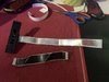
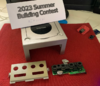
Attached screenshot of the current shell I will be using for the project.
 

Attachments

RDNoob26

.
2023 1st Place
Joined
May 3, 2022
Messages
36
Likes
98
Location
Dominican Republic
Portables
G-boy Wii, VariaPAD
Just a quick update:

I am currently working on the Blueretro part of this project to connect bluetooth controllers to the Wii side of the project.

Here is a picture of the initial wiring.

Front panel blueretro.JPG


And also an slightly trimmed heatsink I'm planning to use.

I have an idea to attach the heatsink and custom regulators using some kind of 3d printed bracket, so I can also include the power and hdmi connectors.
 

RDNoob26

.
2023 1st Place
Joined
May 3, 2022
Messages
36
Likes
98
Location
Dominican Republic
Portables
G-boy Wii, VariaPAD
Another update:

So I had some free time today and started to wire the Gamecube front panel with Blueretro to the no yet trimmed wii to test how it works.

I was able to control all 4 ports:

IMG_9972.JPG


Here are the pictures of the controllers connected:

IMG_9971.JPG


The Gamecube controller also works even if the ports are used, as it has priority on the bus:

IMG_9973.JPG


Next step is to trim the wii, and wire up the HDMI adapter, but I might do the 3d printed bracket to hold the stuff first.

Stay tuned!
 

RDNoob26

.
2023 1st Place
Joined
May 3, 2022
Messages
36
Likes
98
Location
Dominican Republic
Portables
G-boy Wii, VariaPAD
Hello my people,

Here is a quick update of the project.

I noticed that I can keep the switch dock board at the same position, it uses a 30 pin 20706 60V VW-1 flex cable, so I am going to buy a longer one online to be able to keep it there.

As for the wii side, I am going to use the following layout so here is an example of where everything will end up at, as I am going to start doing the design of the 3d printed holder for the board.

Here it is with a trimmed board (not the one going to be used on this project), the custom regulators, HDMI board and USB C board.

IMG_0062.JPG
IMG_0063.JPG
IMG_0065.JPG


I will be posting the 3D design pictures to keep you updated as I make them.
 

RDNoob26

.
2023 1st Place
Joined
May 3, 2022
Messages
36
Likes
98
Location
Dominican Republic
Portables
G-boy Wii, VariaPAD
Hello my people, I forgot to make an update about an usb ports holder to attach the usb memory card to the wii:

photo_5085007636994305397_y.jpg


It holds the trimmed wii USB port with its screw hole and also has a leg in the right to give it more stability.

Here is how it looks with the memory card inserted:

photo_5085007636994305395_y.jpg
photo_5085007636994305394_y.jpg


As for the memory card itself, nothing too fancy going on here, just a naked USB that fits right in the case, once the hard job of the project is done, I will just hot glue it inside the memory card shell:

photo_5094019835590978519_y.jpg
photo_5094019835590978518_y.jpg


Attached is the STL of this mount, it also has a hole which I will use to screw the wii board for better holding. I now have to design the bracket to hold the trimmed wii board, the custom regulators, usb c and hdmi ports. Though I have not trimmed the wii yet.
 

Attachments

RDNoob26

.
2023 1st Place
Joined
May 3, 2022
Messages
36
Likes
98
Location
Dominican Republic
Portables
G-boy Wii, VariaPAD
I have also received the longer FPC cable for the switch dock circuit, which will allow me to place the USB C in a better position for this project:

photo_5094019835590978533_y.jpg


But it didn't work right away. The pinout is the same and there is continuity in both sides:

photo_5094019835590978532_y.jpg


After further inspection, I noticed that the are some extra pins that go to ground in the port:

photo_5094019835590978537_y.jpg


Some guys in the discord channel helped me to figure it out, those are used for shielding which is needed due to the high speed data transfer. I added some silver tape to the cable and also trimmed the pins to make it the same length as the original switch cable, and it started working right away!

photo_5094019835590978534_y.jpg


I hope this information helps other people that needs to replace the cable.
 

Attachments

RDNoob26

.
2023 1st Place
Joined
May 3, 2022
Messages
36
Likes
98
Location
Dominican Republic
Portables
G-boy Wii, VariaPAD
Hello my people,

I had some spare time today so I went ahead and designed the 3 brackets I was missing to hold the components of this project.

The first one is to hold the 4 custom regulators for the project:

photo_5109849268272868041_y.jpg


It is held by the soldering pins coming out to the other side where I will solder the capacitor and the voltage input.

The second one is to hold the VGA to HDMI converter, usb C power and also a 3.5mm jack which I plan to use to output composite video out of it:

photo_5109849268272868037_y.jpg


I managed to align it to the Switch HDMI port position which is great!.

Last one is a little holder to add more support to the trimmed wii board (The one used on the pictures is for demostration and measurements purposes as I have to trim the board I will use for this.)

photo_5109849268272868036_y.jpg


And last, a few pictures of the general view.

photo_5109849268272868039_y.jpg


photo_5109849268272868035_y.jpg


For the next days, I will be trimming the Wii to start wiring this up.

Attached are the files I designed and printed today.
 

Attachments

RDNoob26

.
2023 1st Place
Joined
May 3, 2022
Messages
36
Likes
98
Location
Dominican Republic
Portables
G-boy Wii, VariaPAD
Hello my people, so today I decided to take the step and trimmed the board. It was a very good trim.

Here are some pictures of the process:

photo_5111981925693762519_y.jpg


I covered the CPU and GPU to prevent dust from coming under those.

I have also uploaded the video of the trim process to youtube here:


Sorry for the focus.

And here is how it turned out:

photo_5111981925693762518_y.jpg


photo_5111981925693762517_y.jpg


I will soon begin to wire the power and video output for testing.

Edit: The trim resistances are really nice as well.

Here are the ones before trimming:

1692313637693.png


And here are the resistances after the trim:

1692313676011.png


Making great progress over here.
 

RDNoob26

.
2023 1st Place
Joined
May 3, 2022
Messages
36
Likes
98
Location
Dominican Republic
Portables
G-boy Wii, VariaPAD
Long time with no updates, I've been busy with some personal things.

I wired up the voltage regulators and USB-C connector to the board,plus the USB drive, though it was not working the first time:

photo_5154577113527987073_y.jpg
photo_5154577113527987074_y.jpg


In addition to that, I added a male JST plug for testing using composite video, which turned out very good. Here is the first boot of the project after the trim:

IMG_0464.JPG


Had to replace the USB wires to a thicker one and it started to work properly, I also soldered some wires to the GC controller port vias to test the inputs:

photo_5154577113527987072_y.jpg


Both the Wired and bluetooth controllers are working so far, I will do some JST plugs to wire the inputs and voltages of the Wii to the front panel.

I even did some RetroBrighting to the front panel:

photo_5154577113527987070_y.jpg


However, after testing the power for some time, it seems like the regulators draw too much power at the beginning causing the switch power adapter to turn off, I will try to add a power switch to give it time to get ready for the load.

Edit: Added HD picture of the Trimmed wii first boot.
 
Last edited:
Joined
Jun 21, 2016
Messages
350
Likes
493
Location
Northern New Jersey
However, after testing the power for some time, it seems like the regulators draw too much power at the beginning causing the switch power adapter to turn off, I will try to add a power switch to give it time to get ready for the load.
Could you take care of this with a sufficiently large capacitor in parallel with the supply?
 

Stitches

2 and a Half Dollarydoos
Staff member
.
.
Joined
Feb 5, 2017
Messages
3,848
Likes
3,025
Location
Banana Bender Land, Australia
Portables
6
Long time with no updates, I've been busy with some personal things.

I wired up the voltage regulators and USB-C connector to the board,plus the USB drive, though it was not working the first time:

View attachment 29590View attachment 29591

In addition to that, I added a male JST plug for testing using composite video, which turned out very good. Here is the first boot of the project after the trim:


Had to replace the USB wires to a thicker one and it started to work properly, I also soldered some wires to the GC controller port vias to test the inputs:

View attachment 29592

Both the Wired and bluetooth controllers are working so far, I will do some JST plugs to wire the inputs and voltages of the Wii to the front panel.

I even did some RetroBrighting to the front panel:

View attachment 29593

However, after testing the power for some time, it seems like the regulators draw too much power at the beginning causing the switch power adapter to turn off, I will try to add a power switch to give it time to get ready for the load.
How much current is your supply rated for? Are you taking 5v or 9v from it?
 

RDNoob26

.
2023 1st Place
Joined
May 3, 2022
Messages
36
Likes
98
Location
Dominican Republic
Portables
G-boy Wii, VariaPAD
How much current is your supply rated for? Are you taking 5v or 9v from it?
The original Nintendo switch power adapter is rated for 15v at 2.6A

Which should be enough as the original Wii power brick was 12v at 3.7A

I'm using an USB C adapter that comes with the chip that tell the Nintendo switch power adapter to go with the full 15V, maybe it takes some milliseconds to make the change.

I'll test by adding a power switch today
 

RDNoob26

.
2023 1st Place
Joined
May 3, 2022
Messages
36
Likes
98
Location
Dominican Republic
Portables
G-boy Wii, VariaPAD
Could you take care of this with a sufficiently large capacitor in parallel with the supply?
I was thinking about this too, I have some big capacitors around I use for Drones so I will do this in addition to the power switch and see how it goes.
 
Joined
Jun 21, 2016
Messages
350
Likes
493
Location
Northern New Jersey
I know it's a bit late in the game, but it might be cool to mux the controller and HDMI ports to switch back and forth depending on which console is on. Maybe making use of the lid switch as a trigger? Perhaps for a future revision.
 

RDNoob26

.
2023 1st Place
Joined
May 3, 2022
Messages
36
Likes
98
Location
Dominican Republic
Portables
G-boy Wii, VariaPAD
I know it's a bit late in the game, but it might be cool to mux the controller and HDMI ports to switch back and forth depending on which console is on. Maybe making use of the lid switch as a trigger? Perhaps for a future revision.
Sorry, I don´t understand the suggestion, can you try to explain it better please?
 

RDNoob26

.
2023 1st Place
Joined
May 3, 2022
Messages
36
Likes
98
Location
Dominican Republic
Portables
G-boy Wii, VariaPAD
How much current is your supply rated for? Are you taking 5v or 9v from it?
Could you take care of this with a sufficiently large capacitor in parallel with the supply?

I went ahead and added the power switch, used the one that came in the Gamecube I sacrificed for this, seems like the power issue is fixed now, here are some pictures about how it ended up:

IMG_0739.JPG
IMG_0738.JPG
 

Stitches

2 and a Half Dollarydoos
Staff member
.
.
Joined
Feb 5, 2017
Messages
3,848
Likes
3,025
Location
Banana Bender Land, Australia
Portables
6
The original Nintendo switch power adapter is rated for 15v at 2.6A

Which should be enough as the original Wii power brick was 12v at 3.7A

I'm using an USB C adapter that comes with the chip that tell the Nintendo switch power adapter to go with the full 15V, maybe it takes some milliseconds to make the change.

I'll test by adding a power switch today
Have you verified that you're getting 15v from the Switch charger with that adapter?
 

RDNoob26

.
2023 1st Place
Joined
May 3, 2022
Messages
36
Likes
98
Location
Dominican Republic
Portables
G-boy Wii, VariaPAD
Here is an update about the project.

The Wii is ready my friends, everything is working properly:

- HDMI with VGA input.
- Composite video over a 3.5mm connector using an small switch to turn off vga.
- All 4 Bluetooth and wired controllers.
- Nintendo Switch power adapter with its 15V

I had changed the video wires to the wifi antenna cables and it took away all the interference I was getting. Next step is to install the proper heatsink and fan I will use and also to design some parts of the case.

Here are some pictures of the wii with all the wires that were pending to be added:

photo_5177006635338541867_y.jpg
photo_5177006635338541866_y.jpg


photo_5177006635338541865_y.jpg
photo_5177006635338541868_y.jpg


Now I need to start designing the 3d printed parts I am missing to finish this build.
 
Top