void
.
- Joined
- Jan 8, 2022
- Messages
- 40
- Likes
- 1
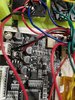
Hi, I was working on my g wii and the composite worked before, when trying to put it together the composite does not work anymore.
")
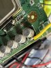
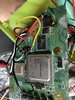
Cleaned up the residue and changed the composite to a different spot on the wii. Still does not work but looks a lot better now.Did you wire the mode pin to 3v3? Oh doesn’t look like it. That disables composite output.
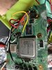
however, from your photos the board looks like it needs a good scrub down with ipa and a brush.. I’d start there and inspect all your joints. Clean all
That residue and see where you’re at then
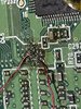
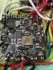
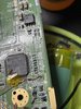
Thanks for the tip, I trimmed down the wires and made sure they were not touching any other things but still does not work.View attachment 22302
The wire on the left looks like it's shorting against a neighbouring via. Also your tinned tips for these wires are a bit long. Ideally you only want 1-2mm of wire exposed to prevent this kind of thing
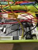
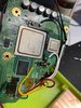
I am getting the right voltage for 1 V, 1.15 V and 3.3 V but not 1.8 V, nothing on 1.8 V. I don't know if that is supposed to happen because I have a PMS lite. I am also getting 3.3 V on U10.Test your voltages at each capacitor where PMS voltage wires connect to the Wii. Also, check for 3.3 V at U10 out to via. What are those readings?
What is the behavior of the composite video? Is it a black screen? Just static? No signal? You said it had worked before...What is the wii trimmed at that point?
You still need to connect 1.8v with PMS lite, Its needed as a reference.I am getting the right voltage for 1 V, 1.15 V and 3.3 V but not 1.8 V, nothing on 1.8 V. I don't know if that is supposed to happen because I have a PMS lite. I am also getting 3.3 V on U10.
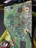
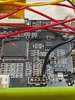
Can you upload pics of everything you changed?Well now it does not work, I was fixing the controls and then 1.8 V came off so I soldered it to the top of c5 and it worked but then i screw it in and then a ground wire came off so I resoldered it but now it does not work
Read thru this https://bitbuilt.net/forums/index.php?threads/wii-trim-resistances.2602/I did some testing and the 1.15 V not connected to the wii is 1.15 V but when it is connected to the wii its 0.03 V. Also Where would I test resistance.