I'M BACK!!!
Some of you may remember me from my 2025 BitBuilt Summer Building Contest project, the Sega Genesis 4. Just a few weeks ago, myself and many other members of the BitBuilt and Benheck.com communities exhibited our work at the Midwest Gaming Classic in Milwaukee, which was an absolutely life-changing weekend. The Genesis 4 drew a lot of attention from convention-goers and fellow modders alike, and in the time since then many people asked me what I will do next. To be honest with you, I really wasn’t sure I could (or wanted to) do another project of that (or any) scale again.
.webp")
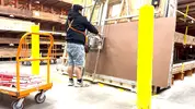
This is me on top of the world at MGC 2026
You see, I’ve been attending the Midwest Gaming Classic on and off for the past 17 years, and this was the first year I’d actually created (successfully) and brought something to showcase. Attending the show as an exhibitor was a totally different experience than any other year. There certainly was significantly more cost associated, both with funding the actual project and staying/parking/eating for the longer duration. There was also a lot more stress, with figuring out how exactly I wanted to present my project, the logistics of transporting it to and from the show, and worrying about if everything was going to work when I got there. Also, I was a bit worried about my experience at the show, knowing that I'd feel obligated to stay pretty close by and nervous about venturing off to explore the other areas. Leading up to that last weekend in April, I was certain that this would be a “one and done” experience for me. I was looking forward to not having to go through all of that again.
Well, all of that changed once the show actually kicked off. The amount of positive interaction I had with attendees, the connections I made with the rest of the community, and the euphoria I experienced actually being constantly surrounded by people who genuinely want to talk about the hard work I did so many months earlier was intoxicating. I had strangers recognize me from my social media posts. I had old friends I hadn’t seen in years pop by to see it. I had family members come to support me. I got to speak directly with the MGC organizers and the curators of other rooms at the show about my favorite things. I was even featured in several other creators' videos. All of it was extremely gratifying, and I made more new connections than I can count even now.

A 12 year old kid and his dad asked for my autograph!! Like I said... LIFE CHANGING!!
Once I was back home and fully recovered, I knew that the road didn’t end there. What I had just accomplished was absolutely incredible to me, but I knew I still had more to give. The one thing I didn’t have was an idea. I certainly learned a lot from working on the Genesis 4, and I knew I wanted to work on another cabinet, but I was absolutely striking out on how I could possibly follow it up. I didn’t want to do another Genesis build, but I honestly didn’t have a deep personal connection to any other console besides the Sega Genesis. I didn’t want to do another 4-player build, since it introduced all sorts of added size and complexity.
I knew that whatever I worked on next had to meet three basic conditions to make it worth building:
1) It had to have a clever name
2) It had to be something I would feel inspired to make artwork for
3) It had to have a feature that made it unique or a “World’s First”
So I spent days and days trying to think of a name first. This might be a bit of a non-traditional workflow, but honestly it’s just how my brain operates. First the name and then the rest evolves out of it. I was going through a list of other retro consoles in my head, and one day it finally came to me. Super Nintendo Chalmers.

I’ve been a huge Simpsons fan my entire life. Probably one of my top 5 fandoms. In Season 10 (in my opinion the last actually good one) Episode 7, “Lisa Gets an A”, there is a scene where Principal Skinner and Superintendent Chalmers take Lisa into the school’s computer lab, where Ralph Wiggum is “learnding” how to spell on the school’s lone COLECO computer. Ralph says hi to Lisa, and then turns to the superintendent and says “Hi, Super Nintendo Chalmers.” That’s it, it’s just a one-liner. It’s a stupid joke from a single episode, but it was exactly the inspiration I needed.
Now, I’m not the first person to take this one-off joke and turn it into a meme project. A 2017 reddit post from u/SpicySNES shows off a custom paint job he commissioned on an actual Super Nintendo, done by an artist named Zoki64. Images of this custom console went somewhat viral around that time and still pop up in Google results when searching that phrase. The thing about this one is that, while it’s very well done, it’s just a case mod. Plus they didn’t even do it themselves (lame). It looks really dope, but it doesn’t actually bring Super Nintendo Chalmers to life.
I think that I can actually bring him to life.

u/SpicySNES's Super Nintendo Chalmers from 2017
Okay, So I’ve got the name. That’s condition #1. Now what about the design and art?
One of the things I was most proud of with the Genesis 4 was the custom full-art vinyl wrap and the assets I created for the presentation. I spent countless hours in Photoshop and Premiere/OBS last summer and in the weeks leading up to MGC making sure everything was absolutely stunning. I am an art school graduate (survivor), so naturally the first thing I did was sketch out some concept art and cabinet designs.
One thing I knew I wanted to do differently than the Genesis 4 was that I wanted to build this cabinet completely from scratch. This is not going to be a modded Arcade1Up. This is not going to use wood from another structure. This is going to be 100% custom. I knew I wanted it to be roughly the same size/shape as my previous build, both so that it looked natural next to it in my apartment, and so that I knew I could transport it by myself. I also knew I wanted it to be a little less wide, since the 4 player control deck of the Genesis 4 barely fit through standard doorways. I spent the first few days sketching out rough dimensions for a cabinet, building those physical pieces out in a 3D model, and then nailing down the size of the individual pieces so I could begin actually decorating it.


Showing the progression from drawing to early modeling to completed design
I knew that it would need good branding. Something more significant than just slapping stock Simpsons art onto a cabinet. After I nailed down the font/logo choices, I began assembling composites of reference artwork in Photoshop. I decided early on that I wanted to hand draw all of the elements (Apple Pencil on iPad) to give it that authentic “Golden-Era Simpsons” feel. With the Genesis 4, the first piece I designed was the marquee, so I figured I’d start with that this time around too.

Marquee Design
For the Marquee, I decided to combine imagery of Superintendent Chalmers with some Nintendo flair. I tried a few different versions of this, and settled (for now) on this design. The base is a blue sky with clouds, referencing the show’s opening animation. The ground plane is directly referential to the environment of Super Mario World, which was a pack in title for the console for some time. Flanking the left and right sides are drawings of Chalmers himself, providing a strong visual anchor to the edges of the piece. Of course, featured in large bold text, is the name of the project itself. I chose this particular shade of pink for the Super Nintendo logo not only because it pairs well with the rest of the artwork (think of the Simpsons pink donut), but also because it will perfectly match the T-molding I purchased for the panel edges (more on that later).

Side Art Design
Alright, next it was Side Art time. Since this is the largest art piece on the entire cabinet, I knew it had to be special. I chose a still from the Steamed Hams segment from Season 7 Episode 21 “22 Short Films About Springfield” for the main part. It features the superintendent inspecting the patented SkinnerBurger©️, which he is originally told is called a Steamed Ham, despite the fact that it is obviously grilled. I gave him a bit of flair with a pink Mario-Style hat to tie it in with Nintendo a little bit more. You may also notice the subtle alternate SNES logo behind him, which gradually fades into the same sky-blue towards the top. The rest of the negative space I filled with a bunch of Steamed Hams and fries falling from the sky, just because I thought it was goofy. I only actually drew 3 different hams and fry designs, and just rotated and repeated the design to save time, as hand drawing all of those assets is extremely time consuming.


Bezel and Kickplate design
Next I decided to work on the Bezel and Kickplate art. These two pieces are designed to give the cabinet sort of a “Simpsons Living Room” vibe. For the kickplate, I decided to make a vector drawing of a stylized SNES console with pink accents, replacing the usual purple. For the background, I used an image of a carpet and blended that with a solid color layer below to match the exact shade of teal that is in their living room, and of course, the bezel is a redesigned version of the Simpson’s living room TV.

Control Panel Design
The final piece was the Control Panel. For this, I tried many different designs, but the one I settled on is probably the least Simpson-y thing on the whole cabinet. I really wanted to pay homage to the Super Famicom in some way, especially since I plan on having the cabinet be fully compatible with both North American and Japanese cartridges. I am really drawn to the color scheme of the Super Famicom controllers, as I feel that the buttons are much more clearly indicated and I’m really big on keeping control panel design minimal. The Japanese text (according to Google Translate) literally says “Chalmers”, so I thought it was a fun subtle way to tie in the Simpsons theming while also giving it that classic look everyone will instantly recognize.
Now that condition #2 was met, I needed to come up with something that made it unique. Besides the aggressively themed artwork, what really is going to set this apart from just being a “pretty” console? It’s not going to be 4-player, that idea I had scrapped early on. I thought long and hard about what I could do to embrace the meme, and I think I came up with a pretty good solution.
My first idea was a custom startup animation. Now, this is something that would be easy to do if I were just taking the easy route of emulating, but gets infinitely more complicated when you’re dealing with real hardware. How would I get a specific video to play when the console turns on? Also, how would I make sure that after the video concludes, there is a seamless transition into the startup screen of the game? I knew that I’d have to integrate a second device to accomplish this. I looked into controller boards for Digital Signage, but they were expensive and harder to customize. What I eventually settled on was the Raspberry Pi Zero 2 W.

A Raspberry Pi Zero 2 W
I chose the Pi because I know a lot of people really like them, and that they are extremely customizable. I found that the Zero 2 W had all the technical capabilities to accomplish what I wanted, but I still needed to figure out how to transition from that to the actual console. I shopped around and decided to buy an Auto HDMI Switcher. The idea being that the Pi would play the short animation, turn off its HDMI signal, and the switcher would detect it was no longer “live” and auto-switch to the SNES (via the RetroTINK 5x Pro, naturally). Seems like a slam dunk, right?

The stupid Auto HDMI switcher I bought
WRONG!! Looking back, it does seem too good to be true. Plus, that solution would have meant that I lose however many seconds from the opening sequence of whatever game I was playing, which is also a no-go. You see, the HDMI switcher really only knows to switch automatically when it detects that a new source SENDS a signal, not when another drops it. That really sucked because that single component was like $60, and I know that a “dumb” switcher would be just as useful if I was going to manually control it anyways. Okay, so how do we get this to all play nicely together? Well, that’s where my old friend the RELAY comes in…

A 4-Channel Relay Module
I used a total of 42(?) relay channels in my last build (5x 8ch, 2x 1ch I think) to control the vast network of control signal routing. That was honestly the greatest engineering feat if you ask me. Now, there certainly are more elegant solutions, but for someone who was basically starting with zero knowledge of electronic switches a little over a year ago, I was extremely proud of my extremely mechanical solution to that problem. Well wouldn’t you know that a RELAY was once again going to bail my ass out. I started with just one relay channel, but decided pretty quickly that I’d need two to get it right.
I luckily already had a spare 4-channel relay left over from last summer. By utilizing the GPIO pins on the Pi Zero, I’d be able to precisely time the control signals to the relay to do exactly what I needed. The first channel would be used like a time-delay switch to start the console just as the opening animation is ending, and the second channel would be used to temporarily “pulse” the HDMI switcher to trigger an input switch just after. This way, the video would play, and then it’d seamlessly fade to black and the first screen of the game would come right after, as if it was built right into the console!
Demonstrating the Relay Timing
But the fun doesn’t stop there. Since I had already committed to adding the Pi, I thought it’d also be fun to have a Chalmers soundboard. I bought an illuminated 30mm yellow pushbutton that I’m planning on putting front and center on the vertical face of the control panel (similar to how I had my two latching pushbuttons on the Genesis 4). This button will play a Superintendent Chalmers sound clip every time it is pushed, completely independent of what the rest of the cabinet is doing. To accomplish this, I had to hook up a separate USB sound card to the Pi, and I’ll have a separate mono amp and speaker inside so that it can happen independently. For now, I’ve got 10 audio clips from the Steamed Hams segment loaded in, and for now they also play sequentially, but I may change that later.
Demonstrating the Soundboard Functionality
BUT WAIT, THERE’S MORE: Since we’re already fully leaning into the meme, I’ve also added a second function to the yellow button. If you press and hold it for 3 seconds, it plays the Steamed Hams clip in its entirety. This “easter egg” functionality was a bit complex to integrate, as it should happen regardless of the state the cabinet is in. So, if the cabinet is in “SNES OFF” mode, it simply launches the video. If the cabinet is currently running a game, it rolls the video (with a few seconds of black “pad” beforehand) triggers an input switch back to the Pi, and plays the video while keeping the game running in the background. At the conclusion of the clip, it simply returns to whatever state it was in beforehand. You can also manually bail out of it by holding the button for 1 second.
Demonstrating the Steamed Hams Easter Egg
OKAY, so what are the goals with this project? Well, I’m going to plan to have the full, custom made cabinet done by the end of the contest! I’ve already tested all the logic, and while I will continue to improve on that over time, I think it’s pretty clear that I’d like it to be 100% complete and functional by the end of summer. The hardest parts will surely be the custom cabinet construction, as that was something I didn’t have to figure out last time. At the same time though, I do think I am removing a lot of complexity, both from not having to deal with any 4-player configurations or custom signal routing, and due to the fact that I’ve got a year of arcade building experience under my belt! I do feel like I have a much clearer picture of what works and what doesn’t. I have much more familiarity with the components of an arcade cabinet, how they interact with each other, and what mistakes to avoid.
I do plan on adding a similar Livestreaming functionality just like I did with the Genesis 4 in the weeks leading up to MGC. Let’s consider that a stretch goal. I certainly don’t need that to be added to feel that it is complete, but hey, it’d be pretty dope to have that done early since I know how to do it already.

The Livestream from MGC 2026
That’s about all for now! I do have more details/things to document and share, but writing this all out was already a lot. Wish me luck, and I look forward to sharing regular text/picture/video updates with you all once again. If you’ve made it this far, props to you for reading this massive wall of text. I’m looking forward to a great summer with you all, and can’t wait to show you my latest project in person again at MGC 2027.
-Ahron
Some of you may remember me from my 2025 BitBuilt Summer Building Contest project, the Sega Genesis 4. Just a few weeks ago, myself and many other members of the BitBuilt and Benheck.com communities exhibited our work at the Midwest Gaming Classic in Milwaukee, which was an absolutely life-changing weekend. The Genesis 4 drew a lot of attention from convention-goers and fellow modders alike, and in the time since then many people asked me what I will do next. To be honest with you, I really wasn’t sure I could (or wanted to) do another project of that (or any) scale again.
This is me on top of the world at MGC 2026
You see, I’ve been attending the Midwest Gaming Classic on and off for the past 17 years, and this was the first year I’d actually created (successfully) and brought something to showcase. Attending the show as an exhibitor was a totally different experience than any other year. There certainly was significantly more cost associated, both with funding the actual project and staying/parking/eating for the longer duration. There was also a lot more stress, with figuring out how exactly I wanted to present my project, the logistics of transporting it to and from the show, and worrying about if everything was going to work when I got there. Also, I was a bit worried about my experience at the show, knowing that I'd feel obligated to stay pretty close by and nervous about venturing off to explore the other areas. Leading up to that last weekend in April, I was certain that this would be a “one and done” experience for me. I was looking forward to not having to go through all of that again.
Well, all of that changed once the show actually kicked off. The amount of positive interaction I had with attendees, the connections I made with the rest of the community, and the euphoria I experienced actually being constantly surrounded by people who genuinely want to talk about the hard work I did so many months earlier was intoxicating. I had strangers recognize me from my social media posts. I had old friends I hadn’t seen in years pop by to see it. I had family members come to support me. I got to speak directly with the MGC organizers and the curators of other rooms at the show about my favorite things. I was even featured in several other creators' videos. All of it was extremely gratifying, and I made more new connections than I can count even now.
A 12 year old kid and his dad asked for my autograph!! Like I said... LIFE CHANGING!!
Once I was back home and fully recovered, I knew that the road didn’t end there. What I had just accomplished was absolutely incredible to me, but I knew I still had more to give. The one thing I didn’t have was an idea. I certainly learned a lot from working on the Genesis 4, and I knew I wanted to work on another cabinet, but I was absolutely striking out on how I could possibly follow it up. I didn’t want to do another Genesis build, but I honestly didn’t have a deep personal connection to any other console besides the Sega Genesis. I didn’t want to do another 4-player build, since it introduced all sorts of added size and complexity.
I knew that whatever I worked on next had to meet three basic conditions to make it worth building:
1) It had to have a clever name
2) It had to be something I would feel inspired to make artwork for
3) It had to have a feature that made it unique or a “World’s First”
So I spent days and days trying to think of a name first. This might be a bit of a non-traditional workflow, but honestly it’s just how my brain operates. First the name and then the rest evolves out of it. I was going through a list of other retro consoles in my head, and one day it finally came to me. Super Nintendo Chalmers.
I’ve been a huge Simpsons fan my entire life. Probably one of my top 5 fandoms. In Season 10 (in my opinion the last actually good one) Episode 7, “Lisa Gets an A”, there is a scene where Principal Skinner and Superintendent Chalmers take Lisa into the school’s computer lab, where Ralph Wiggum is “learnding” how to spell on the school’s lone COLECO computer. Ralph says hi to Lisa, and then turns to the superintendent and says “Hi, Super Nintendo Chalmers.” That’s it, it’s just a one-liner. It’s a stupid joke from a single episode, but it was exactly the inspiration I needed.
Now, I’m not the first person to take this one-off joke and turn it into a meme project. A 2017 reddit post from u/SpicySNES shows off a custom paint job he commissioned on an actual Super Nintendo, done by an artist named Zoki64. Images of this custom console went somewhat viral around that time and still pop up in Google results when searching that phrase. The thing about this one is that, while it’s very well done, it’s just a case mod. Plus they didn’t even do it themselves (lame). It looks really dope, but it doesn’t actually bring Super Nintendo Chalmers to life.
I think that I can actually bring him to life.
u/SpicySNES's Super Nintendo Chalmers from 2017
Okay, So I’ve got the name. That’s condition #1. Now what about the design and art?
One of the things I was most proud of with the Genesis 4 was the custom full-art vinyl wrap and the assets I created for the presentation. I spent countless hours in Photoshop and Premiere/OBS last summer and in the weeks leading up to MGC making sure everything was absolutely stunning. I am an art school graduate (survivor), so naturally the first thing I did was sketch out some concept art and cabinet designs.
One thing I knew I wanted to do differently than the Genesis 4 was that I wanted to build this cabinet completely from scratch. This is not going to be a modded Arcade1Up. This is not going to use wood from another structure. This is going to be 100% custom. I knew I wanted it to be roughly the same size/shape as my previous build, both so that it looked natural next to it in my apartment, and so that I knew I could transport it by myself. I also knew I wanted it to be a little less wide, since the 4 player control deck of the Genesis 4 barely fit through standard doorways. I spent the first few days sketching out rough dimensions for a cabinet, building those physical pieces out in a 3D model, and then nailing down the size of the individual pieces so I could begin actually decorating it.
Showing the progression from drawing to early modeling to completed design
I knew that it would need good branding. Something more significant than just slapping stock Simpsons art onto a cabinet. After I nailed down the font/logo choices, I began assembling composites of reference artwork in Photoshop. I decided early on that I wanted to hand draw all of the elements (Apple Pencil on iPad) to give it that authentic “Golden-Era Simpsons” feel. With the Genesis 4, the first piece I designed was the marquee, so I figured I’d start with that this time around too.
Marquee Design
For the Marquee, I decided to combine imagery of Superintendent Chalmers with some Nintendo flair. I tried a few different versions of this, and settled (for now) on this design. The base is a blue sky with clouds, referencing the show’s opening animation. The ground plane is directly referential to the environment of Super Mario World, which was a pack in title for the console for some time. Flanking the left and right sides are drawings of Chalmers himself, providing a strong visual anchor to the edges of the piece. Of course, featured in large bold text, is the name of the project itself. I chose this particular shade of pink for the Super Nintendo logo not only because it pairs well with the rest of the artwork (think of the Simpsons pink donut), but also because it will perfectly match the T-molding I purchased for the panel edges (more on that later).
Side Art Design
Alright, next it was Side Art time. Since this is the largest art piece on the entire cabinet, I knew it had to be special. I chose a still from the Steamed Hams segment from Season 7 Episode 21 “22 Short Films About Springfield” for the main part. It features the superintendent inspecting the patented SkinnerBurger©️, which he is originally told is called a Steamed Ham, despite the fact that it is obviously grilled. I gave him a bit of flair with a pink Mario-Style hat to tie it in with Nintendo a little bit more. You may also notice the subtle alternate SNES logo behind him, which gradually fades into the same sky-blue towards the top. The rest of the negative space I filled with a bunch of Steamed Hams and fries falling from the sky, just because I thought it was goofy. I only actually drew 3 different hams and fry designs, and just rotated and repeated the design to save time, as hand drawing all of those assets is extremely time consuming.
Bezel and Kickplate design
Next I decided to work on the Bezel and Kickplate art. These two pieces are designed to give the cabinet sort of a “Simpsons Living Room” vibe. For the kickplate, I decided to make a vector drawing of a stylized SNES console with pink accents, replacing the usual purple. For the background, I used an image of a carpet and blended that with a solid color layer below to match the exact shade of teal that is in their living room, and of course, the bezel is a redesigned version of the Simpson’s living room TV.
Control Panel Design
The final piece was the Control Panel. For this, I tried many different designs, but the one I settled on is probably the least Simpson-y thing on the whole cabinet. I really wanted to pay homage to the Super Famicom in some way, especially since I plan on having the cabinet be fully compatible with both North American and Japanese cartridges. I am really drawn to the color scheme of the Super Famicom controllers, as I feel that the buttons are much more clearly indicated and I’m really big on keeping control panel design minimal. The Japanese text (according to Google Translate) literally says “Chalmers”, so I thought it was a fun subtle way to tie in the Simpsons theming while also giving it that classic look everyone will instantly recognize.
Now that condition #2 was met, I needed to come up with something that made it unique. Besides the aggressively themed artwork, what really is going to set this apart from just being a “pretty” console? It’s not going to be 4-player, that idea I had scrapped early on. I thought long and hard about what I could do to embrace the meme, and I think I came up with a pretty good solution.
My first idea was a custom startup animation. Now, this is something that would be easy to do if I were just taking the easy route of emulating, but gets infinitely more complicated when you’re dealing with real hardware. How would I get a specific video to play when the console turns on? Also, how would I make sure that after the video concludes, there is a seamless transition into the startup screen of the game? I knew that I’d have to integrate a second device to accomplish this. I looked into controller boards for Digital Signage, but they were expensive and harder to customize. What I eventually settled on was the Raspberry Pi Zero 2 W.
A Raspberry Pi Zero 2 W
I chose the Pi because I know a lot of people really like them, and that they are extremely customizable. I found that the Zero 2 W had all the technical capabilities to accomplish what I wanted, but I still needed to figure out how to transition from that to the actual console. I shopped around and decided to buy an Auto HDMI Switcher. The idea being that the Pi would play the short animation, turn off its HDMI signal, and the switcher would detect it was no longer “live” and auto-switch to the SNES (via the RetroTINK 5x Pro, naturally). Seems like a slam dunk, right?
The stupid Auto HDMI switcher I bought
WRONG!! Looking back, it does seem too good to be true. Plus, that solution would have meant that I lose however many seconds from the opening sequence of whatever game I was playing, which is also a no-go. You see, the HDMI switcher really only knows to switch automatically when it detects that a new source SENDS a signal, not when another drops it. That really sucked because that single component was like $60, and I know that a “dumb” switcher would be just as useful if I was going to manually control it anyways. Okay, so how do we get this to all play nicely together? Well, that’s where my old friend the RELAY comes in…
A 4-Channel Relay Module
I used a total of 42(?) relay channels in my last build (5x 8ch, 2x 1ch I think) to control the vast network of control signal routing. That was honestly the greatest engineering feat if you ask me. Now, there certainly are more elegant solutions, but for someone who was basically starting with zero knowledge of electronic switches a little over a year ago, I was extremely proud of my extremely mechanical solution to that problem. Well wouldn’t you know that a RELAY was once again going to bail my ass out. I started with just one relay channel, but decided pretty quickly that I’d need two to get it right.
I luckily already had a spare 4-channel relay left over from last summer. By utilizing the GPIO pins on the Pi Zero, I’d be able to precisely time the control signals to the relay to do exactly what I needed. The first channel would be used like a time-delay switch to start the console just as the opening animation is ending, and the second channel would be used to temporarily “pulse” the HDMI switcher to trigger an input switch just after. This way, the video would play, and then it’d seamlessly fade to black and the first screen of the game would come right after, as if it was built right into the console!
Demonstrating the Relay Timing
But the fun doesn’t stop there. Since I had already committed to adding the Pi, I thought it’d also be fun to have a Chalmers soundboard. I bought an illuminated 30mm yellow pushbutton that I’m planning on putting front and center on the vertical face of the control panel (similar to how I had my two latching pushbuttons on the Genesis 4). This button will play a Superintendent Chalmers sound clip every time it is pushed, completely independent of what the rest of the cabinet is doing. To accomplish this, I had to hook up a separate USB sound card to the Pi, and I’ll have a separate mono amp and speaker inside so that it can happen independently. For now, I’ve got 10 audio clips from the Steamed Hams segment loaded in, and for now they also play sequentially, but I may change that later.
Demonstrating the Soundboard Functionality
BUT WAIT, THERE’S MORE: Since we’re already fully leaning into the meme, I’ve also added a second function to the yellow button. If you press and hold it for 3 seconds, it plays the Steamed Hams clip in its entirety. This “easter egg” functionality was a bit complex to integrate, as it should happen regardless of the state the cabinet is in. So, if the cabinet is in “SNES OFF” mode, it simply launches the video. If the cabinet is currently running a game, it rolls the video (with a few seconds of black “pad” beforehand) triggers an input switch back to the Pi, and plays the video while keeping the game running in the background. At the conclusion of the clip, it simply returns to whatever state it was in beforehand. You can also manually bail out of it by holding the button for 1 second.
Demonstrating the Steamed Hams Easter Egg
OKAY, so what are the goals with this project? Well, I’m going to plan to have the full, custom made cabinet done by the end of the contest! I’ve already tested all the logic, and while I will continue to improve on that over time, I think it’s pretty clear that I’d like it to be 100% complete and functional by the end of summer. The hardest parts will surely be the custom cabinet construction, as that was something I didn’t have to figure out last time. At the same time though, I do think I am removing a lot of complexity, both from not having to deal with any 4-player configurations or custom signal routing, and due to the fact that I’ve got a year of arcade building experience under my belt! I do feel like I have a much clearer picture of what works and what doesn’t. I have much more familiarity with the components of an arcade cabinet, how they interact with each other, and what mistakes to avoid.
I do plan on adding a similar Livestreaming functionality just like I did with the Genesis 4 in the weeks leading up to MGC. Let’s consider that a stretch goal. I certainly don’t need that to be added to feel that it is complete, but hey, it’d be pretty dope to have that done early since I know how to do it already.
The Livestream from MGC 2026
That’s about all for now! I do have more details/things to document and share, but writing this all out was already a lot. Wish me luck, and I look forward to sharing regular text/picture/video updates with you all once again. If you’ve made it this far, props to you for reading this massive wall of text. I’m looking forward to a great summer with you all, and can’t wait to show you my latest project in person again at MGC 2027.
-Ahron