Worklog Yet another Ashida Build

Joined
Jun 17, 2022
Messages
36
Likes
24
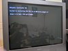
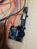
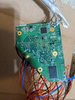
I had been wanting to build a portable for a while and I recently found a deal on a wii in significantly better cosmetic condition than my HDMI modded one (which was spotless internally when I got it but the exterior looked like someone tried to buff out a scratch with 120 grit sandpaper) but with a defective optical drive and some rust starting to form on some of the ports, so I figured it was time to build a portable and swap the case on my other wii. I got the wii I am using for the portable in the mail today along with various other parts, so I got the softmod installed along with RVLoader, then I ran into my first issue. I installed the VGA patch when I installed RVLoader, but that disabled component output, and I apparently don't have any wii composite cables, just way too many component ones. I thought this wouldn't be too much of an issue, figuring component was disabled but the guide didn't say anything about s-video, so I could just plug the green cable into a composite input on my TV to send a luma signal that is also used for s-video, which the tv should interpret as a black and white composite signal, but that didn't work, so I ended up trying to crack open the casing on my crappiest wii component cable so I could move the green signal over to composite and test out the RVLoader menu that way. That plan didn't work out so well, the casing was way too durable, it took forever to break my way through the several layers of nested casings, and when I finally got through it all I found they just pumped the whole thing full of molten plastic like hot glue on a poorly implemented console mod, and I somehow managed to mangle the pins on the interior of the connector without damaging the exterior, so I just chopped the whole thing off and stripped back the insulation and soldered one of the coaxial cables directly to pin 3 of the AV connector on the wii motherboard so I could test that my RVLoader install was working.
PXL_20220618_232746421.jpg
PXL_20220618_232802119.jpg


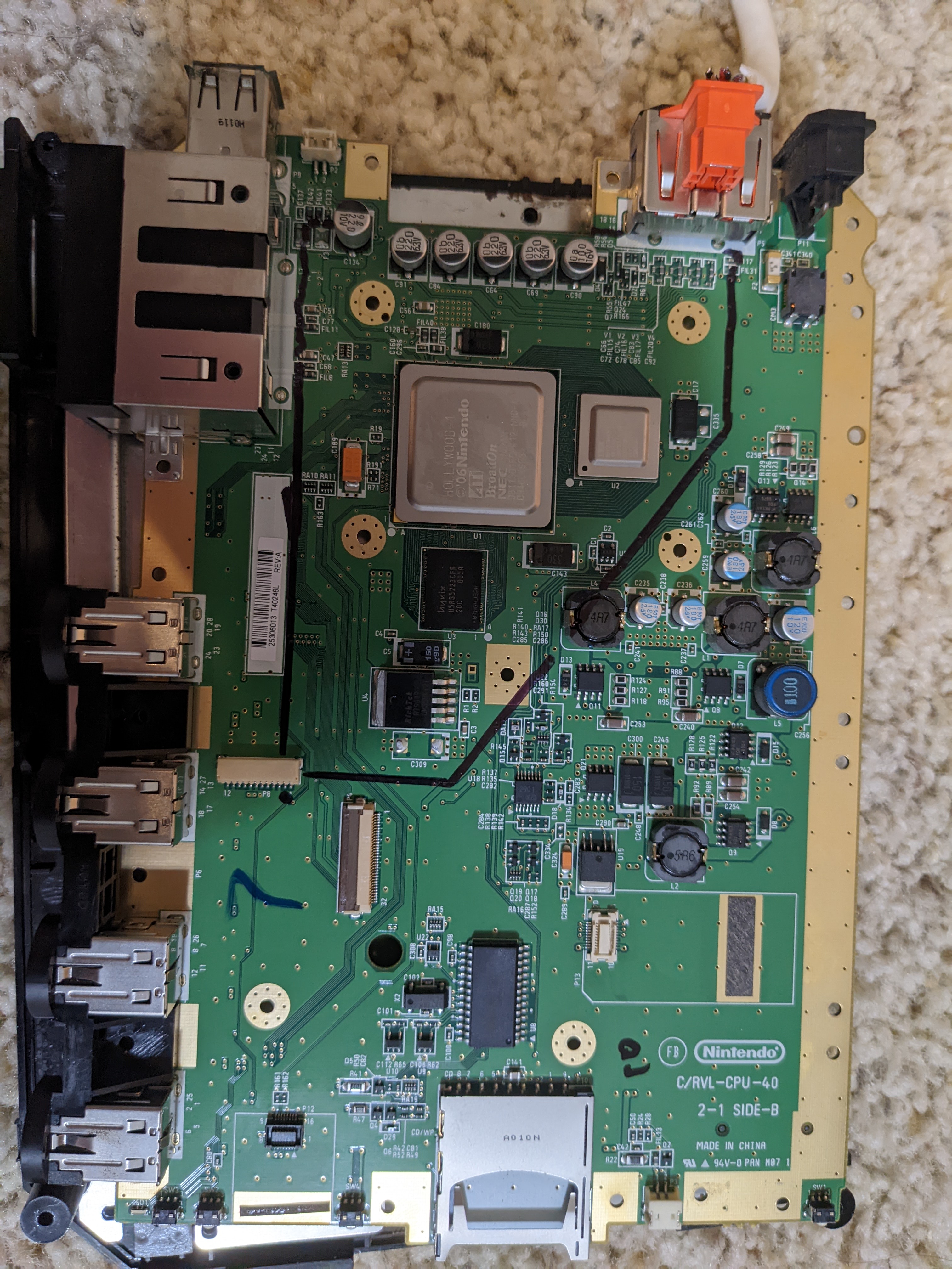
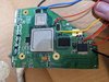
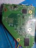
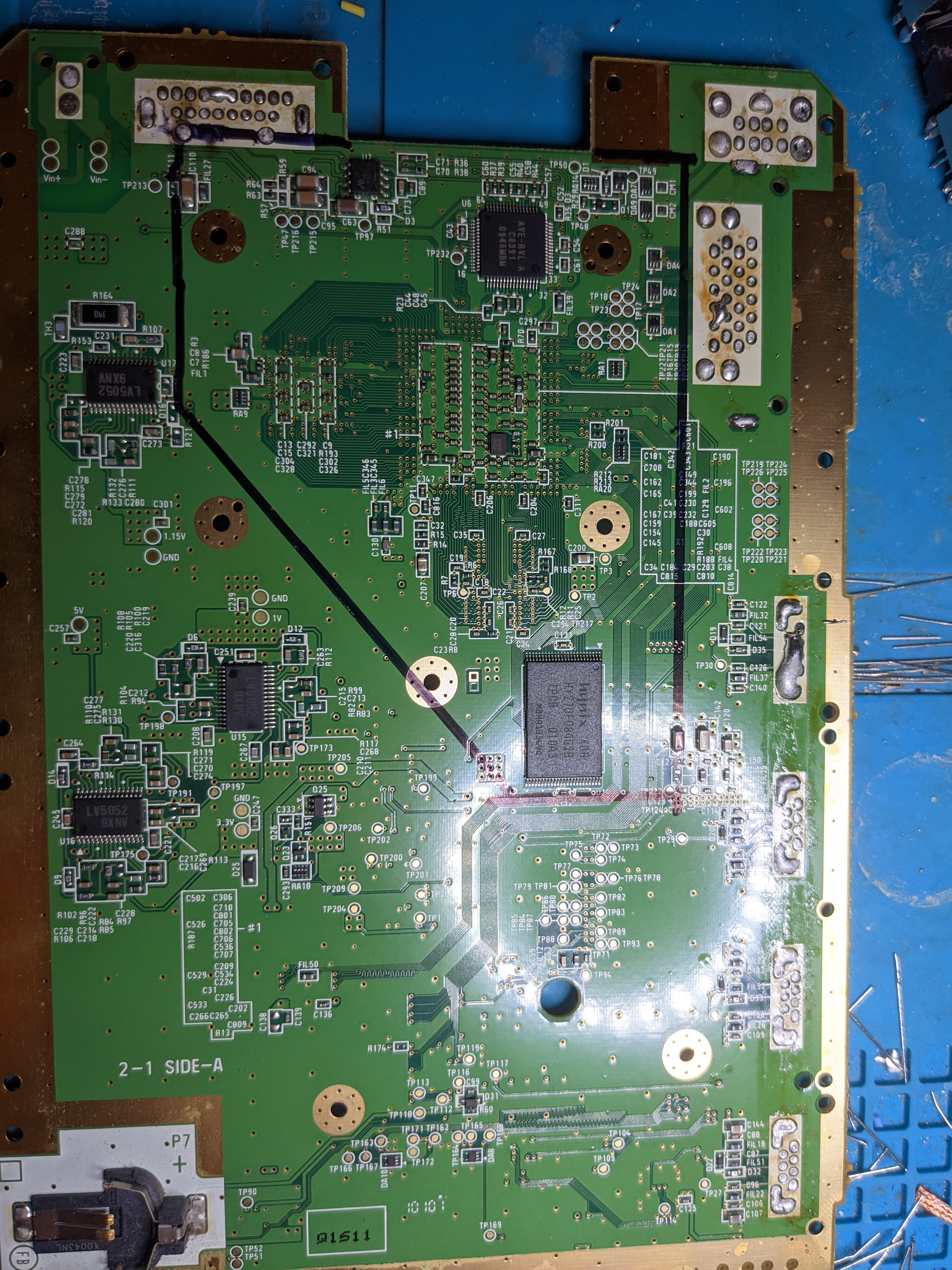
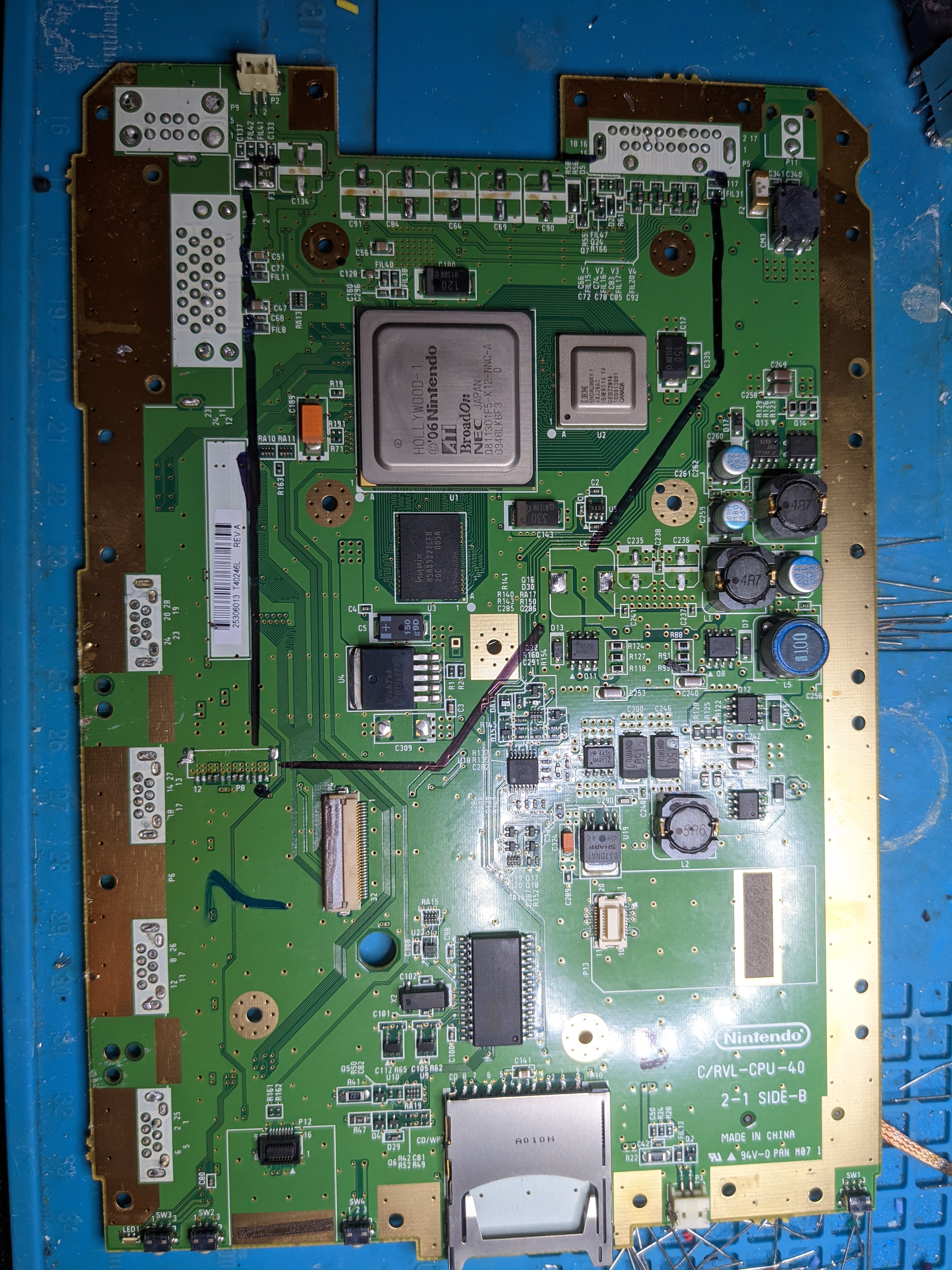
After that I got my wii and gamecube backups moved over to my flash drive and made sure they would load, and I disassembled my HDMI modded wii while I waited, but by then it was getting dark outside and I would rather not do my trim inside and get the dust all over the place, so I just marked out my lines for the trim, desoldered components that might get in the way when doing the trim, and still had plenty of time left in the day so I desoldered all the ports so I would have plenty of room while doing the trim. My cheap $40 hot air station was not at all happy with that process, at 350C it wasn't producing enough heat to deal with the ground planes so I had to crank it to 400C for the memory card port and the fan was struggling to keep temperatures that high, but I eventaully managed for the most part, there were a few places where I just had to lift the port enough to slip some flush cutters under it and snip what was still stuck. It was completely unnecessary but I had time and it should make things a bit easier for me tomorrow.

PXL_20220619_002932997.MP.jpg
PXL_20220619_002910535.jpg


Once I finished that I cleaned up the shell from the wii I am planning on hacking because it had some pretty heavy dust buildup, luckily it was only dust. When it dries I will put the HDMI modded wii back together using the best parts from each shell and tomorrow I will start on my trim. I should be getting the ashida PCBs in the mail Monday or Tuesday as well as my mouser order and a busted gamecube controller to salvage some parts from. Unfortunately my case order is still an estimated 10-13 days out so I will be waiting on that for a while. I might try to model a battery pack to glue onto the back of the case to accomodate a couple extra cells for more battery life, it would be ugly as hell to have a battery tumour sticking out the back of my handheld, but that didn't stop several console manufacturers from putting them on their controllers and/or handhelds or accessories for them, and I figure with some bondo and a paint job I can at least beat the looks of the game gear PowerBack. I already made one attempt at it, but made two major mistakes, one was thinking I was using 20700s not 21700s and designing around those dimensions and the other was assuming the channels for the batteries only needed to be large enough to fit the nominal dimensions of the batteries, but my cells are larger than the nominal size and I would need a couple extra milimeters for the battery tabs (21700s are supposed to be a 21cm radius and 70mm length, mine were 21.27mm x ~70.5mm, I'm not going to close my calipers on the cells lengthwise because that would short them and be very dangerous).

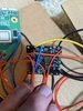
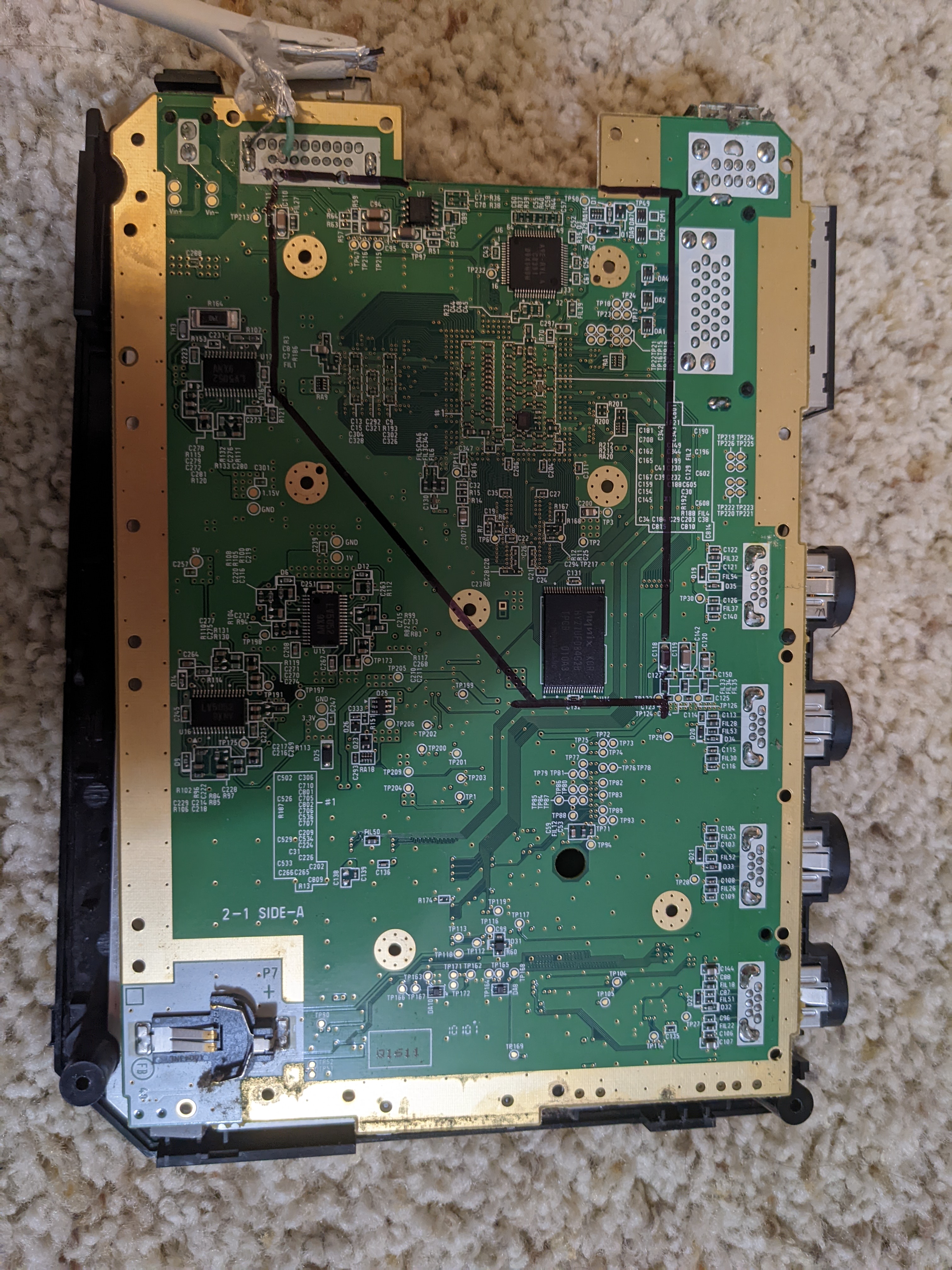
If anyone could double check my lines for the trim I would appreciate it, I have a decent amount of modding experience but I have never done anything that would require a trim like this, other advice would also be helpful, although I don't have much in the way of specific questions besides whether the coaxial conductors salvaged from a VGA cable would be suitable for connecting my VGA signal to the monitor. They can obviously carry a VGA signal as that is what they were designed for, but I'm not sure if they would be too thick, the outer insulation on them is about 2.5mm so I am somewhat worried they might be too stiff, although it would be great if they will work because they are well shielded and color coded for me. If they are too thick I have some scraps of unterminated ethernet cables so I guess I can pull some twisted pairs from that to save myself the effort of twisting wire myself and having to deal with pairs that are matching colors because I only have one color of magnet wire.
 

Attachments

Stitches

2 and a Half Dollarydoos
Staff member
.
.
Joined
Feb 5, 2017
Messages
3,833
Likes
3,018
Location
Banana Bender Land, Australia
Portables
6
Your trim lines look okay. Just make sure when you're cutting by the NAND (and the decoupling capacitor) that you leave a good ~5mm margin and keep your hand steady. You can always sand sides down if the board is too big to fit in your case
 
Joined
Jun 17, 2022
Messages
36
Likes
24
This morning I marked out the lines for an mx relocation and masked that off as well as I could, then did my trim. It went quite smoothly until I got to the 3rd edge I cut, then my dremel glanced off a component and bounced inside the lines. That area is all ground plane on the outermost layer of both sides, but when I closely inspect that cut I can see it also nicked the 2nd layer. Hopefully there wasn't anything important that close to the edge, but I might need to find another donor board. I sanded it anyways in case it still works, although I can't test it until I get the pcbs and screens from 4 layer tech.
PXL_20220619_135314366.MP.jpg
PXL_20220619_135314367.MP.jpg
PXL_20220619_141143881.MP.jpg
PXL_20220619_143502313.jpg
PXL_20220619_143521892.jpg


I also checked the resistances using the values found in the guides, They were all in the right orders of magnitude, but some of them were a ways off, I was getting 70 Ohms where the chart said I should have 116 and 4.5k where it says it should be 7k. Can the values swing that much or do I need to do more sanding?
 

Stitches

2 and a Half Dollarydoos
Staff member
.
.
Joined
Feb 5, 2017
Messages
3,833
Likes
3,018
Location
Banana Bender Land, Australia
Portables
6
You got lucky there. That nike swoosh landed in a place without anything important. The board should be fine.

For the resistances, I don't know how much they vary from board to board, or even trim to trim. But the main important thing is that none of the resistances are single digits or 0. As long as nothing is shorted, you're probably fine. Just make sure you give the board a good brush off before wiring, just in case any copper hairs from sanding are hanging around
 
Joined
Jun 17, 2022
Messages
36
Likes
24
Today I got some 22 gauge stranded wire in the mail (I thought I had some already but the 22 gauge I had was solid core aluminum wire, which definitely wouldn't be suitable, so I had to order a 6 color pack of stranded copper wire and wait on that), so I got the minimum needed to boot wired up and tested my board to make sure it is still working after the trim, which it does. I also put some solder mask on the spot I accidentally cut the board since I had some around for some trace repair on other projects. I am planning on waiting for my case to arrive before I do the rest of the wiring so I can keep the wire lengths as short as is practical, although craftcloud says it hasn't shipped yet and is still estimating 10-13 days remaining, which is the same estimate as it had 9 days ago
 

Attachments

Joined
Jun 17, 2022
Messages
36
Likes
24
Today my 3d prints finally got shipped to me (they are a week late) and it looks like I am going to have to have to wait even longer because they were missing one of the buttons and the case halves are warped pretty badly, all the convex surfaces are covered in concave pits and the halves don't meet up even remotely like they are supposed to, when I try to fit them together the gap between the halves varies between actually fitting right and an opening over 2mm wide at various points around the seam. I sanded it with 80 grit for half an hour and decided it wasn't worth dealing with trying to get a decent finish on these prints, it would take at least another couple sheets of 80 grit to get it sanded smooth enough to paint and at that point it would be too thin, and it would take a whole tube bondo to fill all the pits and gaps between the filament to a degree where I could get a paint job to look halfway decent. At least the interior is close enough to the right dimensions that I can start getting all my wires measured to length and put together, I was able to start on that, although I ran into some issues with the USB board, I was trying to keep the wires as short as possible to avoid a rat's nest but I put the charge wires in the wrong way and there wasn't enough slack so I decided to call it a day. When I get around to continuing this I am going to need to desolder the wires, clean the holes throughly, and do them over, which I am not looking forward to.
PXL_20220706_010640623.jpg
PXL_20220705_230932827.MP.jpg
PXL_20220705_231017173.jpg
PXL_20220705_231050160.jpg
PXL_20220705_231103343.jpg
PXL_20220705_231113198.jpg
PXL_20220705_231156332.jpg
 

Attachments

CrazyGadget

Crazy Helpful, CrazyGadget
.
Joined
Jun 6, 2020
Messages
611
Likes
879
Location
Downing's Closet
Portables
???
For future reference, you don't need 2 wires per pad for CHARGE or GND, or any pad that has 2 through-holes. They are a single piece of copper on the same plane, so they are already connected to each other. 1 wire per pad is plenty if you are using 22awg.
PXL_20220706_010640623.jpg
 
Joined
Jun 17, 2022
Messages
36
Likes
24
I spent some time today test fitting my components and figuring out where to mount my Bluetooth module and mx chip and whole I was planning it out I couldn't find any mention of where to connect the negative terminal of the clock battery for the mx relocation. I checked the g-boy manual to see if I can get any information from there and it looks to me like it is connected to a pin or via on the mx trim's ground plane, but I was having trouble getting a clear look at it in the included pictures. Is that correct? If it is correct could I instead scrape the solder mask off of the ground plane of the main Wii trim and solder a surface mount battery holder to the exposed copper to help anchor it in place since there should be a wire connecting the ground planes of the main trim and the mx trim?
 

Stitches

2 and a Half Dollarydoos
Staff member
.
.
Joined
Feb 5, 2017
Messages
3,833
Likes
3,018
Location
Banana Bender Land, Australia
Portables
6
I spent some time today test fitting my components and figuring out where to mount my Bluetooth module and mx chip and whole I was planning it out I couldn't find any mention of where to connect the negative terminal of the clock battery for the mx relocation. I checked the g-boy manual to see if I can get any information from there and it looks to me like it is connected to a pin or via on the mx trim's ground plane, but I was having trouble getting a clear look at it in the included pictures. Is that correct? If it is correct could I instead scrape the solder mask off of the ground plane of the main Wii trim and solder a surface mount battery holder to the exposed copper to help anchor it in place since there should be a wire connecting the ground planes of the main trim and the mx trim?
All grounds are connected together, so you can run the negative wire anywhere that's convenient for you
 
Joined
Jun 17, 2022
Messages
36
Likes
24
Today I worked on getting the mx and Bluetooth boards relocated and wired up as well as connecting the motherboard end of the various hook up wires I still needed to connect, the ones that require magnet wire were a pain but none of them have me too much trouble, but I did run into a potential issue when I tried to connect the wires for video. I had half a VGA cable laying around from another project so I pulled the color coded coaxial wires from that and started to get them soldered onto the board, I used the pads for the electrolytic capacitors done they give me a nice big pass to work with and there was a wide ground plane right next to it to connect the shielding, then I realized I should check my work with a multimeter to make sure I didn't accidentally short the shielding to the conductor, but when I checked I got continuity between the conductor and ground. After redoing my work a couple times and swapping my coax for some twisted pair wire from Ethernet cable and still getting a short to ground I removed all of my wires from the RGB circuit, wicked up the solder, and checked continuity between the bare pads and ground and I was still getting a short between the pads for r, g, b, and composite video and ground. I also flipped the board over and put my probes directly on the AVE pins and still measured a short to ground. I couldn't see anything that would cause all 4 of those signal paths to short to ground, is this normal behavior when the board is unpowered? If it matters, all the wires for USB, h/vsync, controller, u10, digital audio, and wifi pairing are not connected on the other end, I just left them long and with insulation on the other end so I can trim them to length when I get to that stage.
PXL_20220708_025131968.jpg
PXL_20220708_025119666.jpg
 

CrazyGadget

Crazy Helpful, CrazyGadget
.
Joined
Jun 6, 2020
Messages
611
Likes
879
Location
Downing's Closet
Portables
???
Are you using your multimeter in resistance mode or continuity mode? If you are using continuity, there's a chance it could be beeping even though the correct resistance is there. Iirc, all the RGB and composite lines all have 75 ohm termination resistors, so if you're getting that resistance, that would be right.
 
Joined
Jun 17, 2022
Messages
36
Likes
24
Thank you, I was using continuity mode, I just checked it with resistance mode and they were all 75 ohms, so I guess I will get back to assembling what I can after work.
 
Joined
Jun 17, 2022
Messages
36
Likes
24
I made some more progress today, the case didn't fit together right at all, but I at least used it as a guide to get the wires to a reasonable length, after a bunch of troubleshooting basic mistakes like getting the USB data lines backwards and needing to clear a bridge was needed, but I got it almost working. The screen was finicky but now works, the c stick and face buttons work, and it will boot into Wii and GameCube games. Audio seems not to work, but I only tested headphones (I am holding off on installing the speakers because they will be difficult to remove when I get the new case) and I might just have the volume all the way down or something obvious like that. I will hold off on troubleshooting the audio for now, i plan to do that one I get the new shell pieces so I can install the battery clips and not need to worry about having to dig them out later, which would let me use both hands to troubleshoot (as well as not have one hand in the way of the power switch and volume wheel)
PXL_20220710_000931307.jpg


.
 
Joined
Jun 17, 2022
Messages
36
Likes
24
I got my case replacement in the mail today, I went with clear resin this time, it looks quite nice but I have a much bigger problem. I got my components transferred over to the new case, installed the battery clips, and turned it on to make sure it was working, and I noticed that the battery indicator LED wasn't working. My first step was to probe the voltage pin to check it out was getting enough power, but my probe slipped from the 5v pin and shorted to the data pin and it shut down and left me with a black screen immediately. After removing the battery and cycling the power switch a few times, giving it some time to cool down, reinstalling the battery, and turning it back on I quickly noticed smoke coming out from under the Wii board, I immediately toggled the power switch but the screen was still displaying the rvloader menu, I quickly moved the Wii motherboard out of the way and noticed that a component on the pms lite (which I later identified as L4) was flirting red and the source of the smoke, and then I started trying to remove the battery since the screen was still displaying the rvloader menu. I don't know what to do from here. Would it be safe to replace L4 and if so what should it be replaced with? If not it appears I will be waiting a while because both the full and lite pms boards appear to be out of stock on 4layertech. I am guessing I also need to replace the LED but I have some spare ws2812s I ordered because I wasn't sure if it would be included with the pms lite
PXL_20220719_004619044.MP.jpg
 
Last edited:
Joined
Jun 17, 2022
Messages
36
Likes
24
My replacement PMS-Lite came in today and I got the wires all swapped over, my wii now powers up as expected, so I guess the u10 emulation was fried on the old one since the voltages were correct but the wii wouldn't boot. I do still have a couple issues left to troubleshoot though. My LED doesn't light up in the RVLoader menu or if I launch a game, is it supposed to be lighting up or does it not do anything unless the system is plugged in/low battery/etc. and if so, what is the easiest way to test it? Also I get audio over the headphone jack but not the speakers (I did double check to make sure no headphones were plugged in when I wasn't getting audio on the speakers, so it isn't that. Does this look wired up right? The blue wire goes to A, the red goes to L+, and the black goes to ground but I could have screwed up the pinout. I know shorts are a strong possibility with this much exposed leg, I only left it this to make testing easier since I was having LED issues previously, I will definitely trim the legs and also add some heatshrink if there is room before closing everything up.
PXL_20220728_022011790.jpg
 

Stitches

2 and a Half Dollarydoos
Staff member
.
.
Joined
Feb 5, 2017
Messages
3,833
Likes
3,018
Location
Banana Bender Land, Australia
Portables
6
The LED behaviour is configurable in RVLoader. I'm not sure what the default behaviour is, but you can try changing the LED settings and see if it starts changing colour. If it doesn't then you may have wired the LED incorrectly.

As for the audio, can't really speculate without pictures of the U-Amp and the jack
 
Top