Worklog WiiVision Build

Tron

.
Joined
May 26, 2020
Messages
83
Likes
57
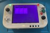
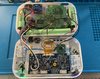
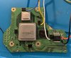
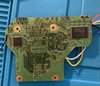
I trimmed my third motherboard. This time I did the U10 relocation before trimming and verified that it boots and composite video works. After trim, I measured the resistance and didn't see any short (1.0V: 214 Ohm, 1.15V: 57 Ohm, 1.18V: 37 Ohm, 3.3V: 16 kOhm). But I am getting no video on the composite. The LCD shows a blue waiting-for-AV-signal screen. What could I be doing wrong? Thanks.
 

Attachments

Gman

RTFDS
Staff member
.
.
.
.
.
Joined
Feb 25, 2016
Messages
1,437
Likes
2,887
If you do not remove the LDO you cannot wire 1.8v from the pms, you can remove this wire.
 

Tron

.
Joined
May 26, 2020
Messages
83
Likes
57
Thanks. Are you saying that I don't need to wire up 1.8 V?
 

Wesk

Undervolting....
Staff member
.
.
Joined
Jul 12, 2017
Messages
869
Likes
2,176
Location
Queensland, Australia
I would keep sanding also, from your pictures I can see a few frays around the edge of the board. The edge of the board should be as smooth as a baby's bottom.
 

Tron

.
Joined
May 26, 2020
Messages
83
Likes
57
Are you saying that I should sand more even though I'm not getting short on the voltage pads? I was afraid that I might make things worse by sanding more.
 

Tron

.
Joined
May 26, 2020
Messages
83
Likes
57
Thanks to Gman, I got the composite video to come on. The TL;DR version is that I used 26AWG to connect the PMS to the Wii. Once I replace the wires with 22AWG, the composite video started working.

Next, I wired up USB and got it working. I then wired up the VGA. The LCD shows the BBLoading screen without the USB thumb drive. But once I plugged in the USB drive, the screen flashes on and off. I can see BBloader's Wii game screen when the screen flashes on.

Does anyone know why the screen is flashing on and off?
 

Tron

.
Joined
May 26, 2020
Messages
83
Likes
57
I figured out the problem with the video. Replacing the 3.3V and ground wires to the LCD display board with 22AWG fixed the problem. Now, on to wiring up the buttons and GC+2.0.
 

Gman

RTFDS
Staff member
.
.
.
.
.
Joined
Feb 25, 2016
Messages
1,437
Likes
2,887
I figured out the problem with the video. Replacing the 3.3V and ground wires to the LCD display board with 22AWG fixed the problem. Now, on to wiring up the buttons and GC+2.0.
3.3v? The screen is suppose to be molded with 5v, can you confirm what you did?
 

Tron

.
Joined
May 26, 2020
Messages
83
Likes
57
Thanks to Gman and others from this forum, I've made some good progress in the last few days. So far I'm able to get the WiiVision to boot from the USB drive and the A/B/X/Y and D-pad are all working. Native VGA is working also but the color is off. Since a picture is worth a thousand words, I'm attaching a couple of photos (please pardon the messy wiring).

Here are some questions that I still have and I'm not able to find from this forum or YouTube videos. Any guidance would be appreciated.

1. How to install the fan from the cooling kit that I bought from the BitBuilt store? Do I just superglue the metal side of the fan to the case?

2. Where do I wire the four buttons (two gray and the + and -) on the front to?

3. How do I wire up the potentiameter from the shoulder buttons to the GC+ 2.0?

4. Is the Joycon joystick click wired up to anything?

Thanks,
Tron
 

Attachments

Tron

.
Joined
May 26, 2020
Messages
83
Likes
57
Can someone tell me if I wired up the joycon breakout board correctly to the GC+? I'm not able to trigger the BBLoader selection wheel/menu when I move the joycon joystick around after booting into BBLoader. Thanks.


IMG_1558.jpg
 
Joined
Jul 14, 2020
Messages
9
Likes
2
Portables
1
It looks like you’ve got the c stick grounded to your screen instead of the gc+ board. I’d check with a multimeter if you’re getting 3.3 volts from the c stick and check the x and y axis move around the stick to see if the voltage is changing. If it’s still not working try the gc+ on a known working wii or the switch adaptor hooked up to dolphin. I’ve had problems with the c stick in the bbloader menu. The issue went away by pressing the reset button. Hope this helps.
 

Tron

.
Joined
May 26, 2020
Messages
83
Likes
57
Thanks for the suggestions. Since the photo was taken, I have rewired the ground to the GC+. But it didn’t make a difference. Just to clarify, when you say 3.3 V from the c stick do you mean to see if I’m getting 3.3V on the x and y wires coming from the stick? Also, when you say switch adaptor, are you referring to something like this? (Y Team Controller Adapter for Gamecube, Compatible with Nintendo Switch, Super Smash Bros Switch Gamecube Adapter for WII U, PC, 4 Port ,Black, W046 )
Lastly, when you say you press reset the problem went away, were you pressing reset while running the GC+ configurator or do you mean something else?
 

Tron

.
Joined
May 26, 2020
Messages
83
Likes
57
I managed to track down the problem with my joysticks to what appears to be a faulty GC+2.0 issue. The GC+ board does not seem to pick up any signal on CY. I tried 3 different joysticks (including one from the BitBuilt store) and 2 different breakout boards (including one from the BitBuilt store) and I get stuck at the last step of the Stick Wizard where you are asked to turn the C stick counterclockwise. Despite my turning the joy stick, the screen just says "Keep turning." At this point is there anything I can do to fix the GC+ 2.0 board or do I need to get a new board?
 

Gman

RTFDS
Staff member
.
.
.
.
.
Joined
Feb 25, 2016
Messages
1,437
Likes
2,887
Did you try the CY stick+breakout on the left stick GC+ connection?
 

Tron

.
Joined
May 26, 2020
Messages
83
Likes
57
I tried that. And the stick and breakout board work when wired to S-side pads. Moreover, the working stick and breakout board on the left has the same problem when wired to the C-side pads.
 

Gman

RTFDS
Staff member
.
.
.
.
.
Joined
Feb 25, 2016
Messages
1,437
Likes
2,887
Ok I guess thats some good news. Is there anything if you go into the controller button monitor? How about cleaning the pcb with isopropyl and scrub with q-tip or toothbrush.
 

Tron

.
Joined
May 26, 2020
Messages
83
Likes
57
I bought the board from BitBuilt store and I cleaned the PCB with IPA. The Stick Wizard still would not finish the last stage. The button monitor does pick up both the x and y movements for both the left and right sticks but the x-x-axis is reversed for both sticks which is why I was trying to use the stick wizard to reconfigure.
 

Gman

RTFDS
Staff member
.
.
.
.
.
Joined
Feb 25, 2016
Messages
1,437
Likes
2,887
If the button monitor isnt showing anything then the stick reconfigure wouldnt do anything. Can you measure the voltage on the axis pads, you should see changing voltage as you move the stick
 

Tron

.
Joined
May 26, 2020
Messages
83
Likes
57
I’ll measure the voltage but to clarify the button monitor does pick up the movementS (both x and y for both sticks). The x-axis is reversed, I.e., when you move the stick to the left the monitor shows the movement to the right.
 
Top