Name TBA. This portable is a collaboration @mokus which I believe will be the most ambitious and integrated portable yet. The idea is simple - design a compact portable with no wires. The execution, well, that's another story. Over the last few months, I've assembled many various designs, all of which have been dropped for one reason or another. The work I have so far for this design has taken bits and pieces of all of my previous "experiments" as its foundation and have had them expanded on significantly.
Many of you have seen my PMS and USBC board design from a while back. The first thing I did was completely redesign these boards from scratch (switching to Altium from Eagle for my CAD work). My main two grievances about the original boards were finding a reasonable way to make the boards fit in a compact design, and the number of wires required to be soldered between the two. So I sought out to address both of these concerns. @mokus proposed an excellent idea: if the horizontal plane is the limiting factor, why not use the vertical axis? The idea here being to "stack" the PCBs using standoffs. That addresses concern #1. To address concern #2, the original plan was to connect the two boards together using FFC cables; something I had planned to do in the original design but ended up dropping due to spacial concerns, which is now a non-issue with the stacked-PCB architecture. However, we came up with an even better idea: to use a stacking self-mating connector on each board. This not only solves the problem of finding an FFC of a very specific length but also enables us to route the USB PD power connection through the connectors, as each pin on the Samtec LHSM series connector we chose is rated for up to 2A.
A few other things have changed in the design as well. The connector for WiirdFlex is integrated on the PMS which will supply power, the thermistor connection, and pull a USB connection from the Wii to send to the USBC board. The MCU has been swapped to an STM32G431KB. I chose this MCU based on a couple of factors: hardware USB support, large flash/RAM size, 3 separate i2c controllers, a small 5x5mm footprint, and because I've been becoming increasingly familiar and fond of ARM. I could go on and on about what this board stack will support, but I think its best if I just put the features in a list:
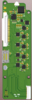
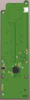
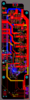
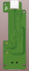
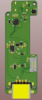
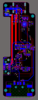
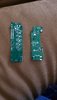
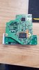
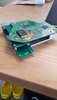
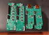
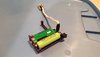
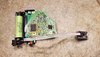
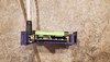
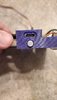
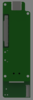
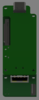
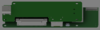
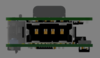
And now for some images of the PCB stack assembly. There were a few challenges in realizing this stack. First, the total height of the stack was constrained by the desire to use a thin (~7mm) cooling solution. If the Wii motherboard is to overhang the PCB stack, the total height of the stack needed to be less than around 12mm, including screw posts used to mount the PCB stack into the case. Using a 2mm screwpost, and 0.8mm PCB thickness for both boards, I'm left with just over 8mm of total height. There are also components on the Wii board, which reduces this height further. Additionally, the mating connectors to connect the two boards only come in certain heights. So I picked a 6.5mm mated connection, ever so slightly taller than the USB A port which sits on the bottom of the USB C board. This also constrained me to place no components on the top of the PMS board which sits below the USB A port. Additionally, I placed no components on the top of the USB C board, to reduce maximum height further. You can see from the images how close it will be.

That's all for now, I will likely be conducting some more review on the PCBs before I go ahead and order them. Afterward, I will be working on firmware until I finish this school quarter (I've admittedly been putting school on the backburner a bit.. I blame either online classes or senioritis). Thanks for reading!
EDIT: Something I didn't consider was that the connector used for WiirdFlex will need to rise in order to release the FFC cable. Therefore, I rerouted the USBC board to support a larger cutout such that the connector won't be limited by the USBC board above it. Updated the images to reflect the changes.
Many of you have seen my PMS and USBC board design from a while back. The first thing I did was completely redesign these boards from scratch (switching to Altium from Eagle for my CAD work). My main two grievances about the original boards were finding a reasonable way to make the boards fit in a compact design, and the number of wires required to be soldered between the two. So I sought out to address both of these concerns. @mokus proposed an excellent idea: if the horizontal plane is the limiting factor, why not use the vertical axis? The idea here being to "stack" the PCBs using standoffs. That addresses concern #1. To address concern #2, the original plan was to connect the two boards together using FFC cables; something I had planned to do in the original design but ended up dropping due to spacial concerns, which is now a non-issue with the stacked-PCB architecture. However, we came up with an even better idea: to use a stacking self-mating connector on each board. This not only solves the problem of finding an FFC of a very specific length but also enables us to route the USB PD power connection through the connectors, as each pin on the Samtec LHSM series connector we chose is rated for up to 2A.
A few other things have changed in the design as well. The connector for WiirdFlex is integrated on the PMS which will supply power, the thermistor connection, and pull a USB connection from the Wii to send to the USBC board. The MCU has been swapped to an STM32G431KB. I chose this MCU based on a couple of factors: hardware USB support, large flash/RAM size, 3 separate i2c controllers, a small 5x5mm footprint, and because I've been becoming increasingly familiar and fond of ARM. I could go on and on about what this board stack will support, but I think its best if I just put the features in a list:
- Only wires to the board are the two short wires that will connect to the battery clips, no wires necessary between the two boards, or to the Wii
- Complete power supply for the Wii and battery management unit, with fuel gauge to receive accurate battery percentage on demand, thermistor connection for over-temperature shutdown, and connection for RGB LED (will be using WS2812B or similar) to indicate charging status, etc.
- Hardware support for i2c connection to the Wii to support features like WiiHUD
- USB PD fast-charging at voltages between 5-15V, automatic PD negotiation on cable plug-in detection
- Integrated internal USB port to store games. The drive is accessible via the USB C port while the console is turned off
- Firmware upgrades via the USB C port; the firmware can be upgraded without ever needing to open the portable
- USB C port can be used to communicate with the STM32 serially at any time, will primarily be used for debugging, but may have some other uses in the future
- Integrate power button
- FFC connection to the rest of the portable
- Vertical, space-efficient layout
And now for some images of the PCB stack assembly. There were a few challenges in realizing this stack. First, the total height of the stack was constrained by the desire to use a thin (~7mm) cooling solution. If the Wii motherboard is to overhang the PCB stack, the total height of the stack needed to be less than around 12mm, including screw posts used to mount the PCB stack into the case. Using a 2mm screwpost, and 0.8mm PCB thickness for both boards, I'm left with just over 8mm of total height. There are also components on the Wii board, which reduces this height further. Additionally, the mating connectors to connect the two boards only come in certain heights. So I picked a 6.5mm mated connection, ever so slightly taller than the USB A port which sits on the bottom of the USB C board. This also constrained me to place no components on the top of the PMS board which sits below the USB A port. Additionally, I placed no components on the top of the USB C board, to reduce maximum height further. You can see from the images how close it will be.
That's all for now, I will likely be conducting some more review on the PCBs before I go ahead and order them. Afterward, I will be working on firmware until I finish this school quarter (I've admittedly been putting school on the backburner a bit.. I blame either online classes or senioritis). Thanks for reading!
EDIT: Something I didn't consider was that the connector used for WiirdFlex will need to rise in order to release the FFC cable. Therefore, I rerouted the USBC board to support a larger cutout such that the connector won't be limited by the USBC board above it. Updated the images to reflect the changes.
Last edited:
")