- Joined
- Dec 16, 2016
- Messages
- 1,122
- Likes
- 2,710
- Location
- The Oregon Wildlands
- Portables
- just so many i am so cool
What specifically do you think you have a short on?
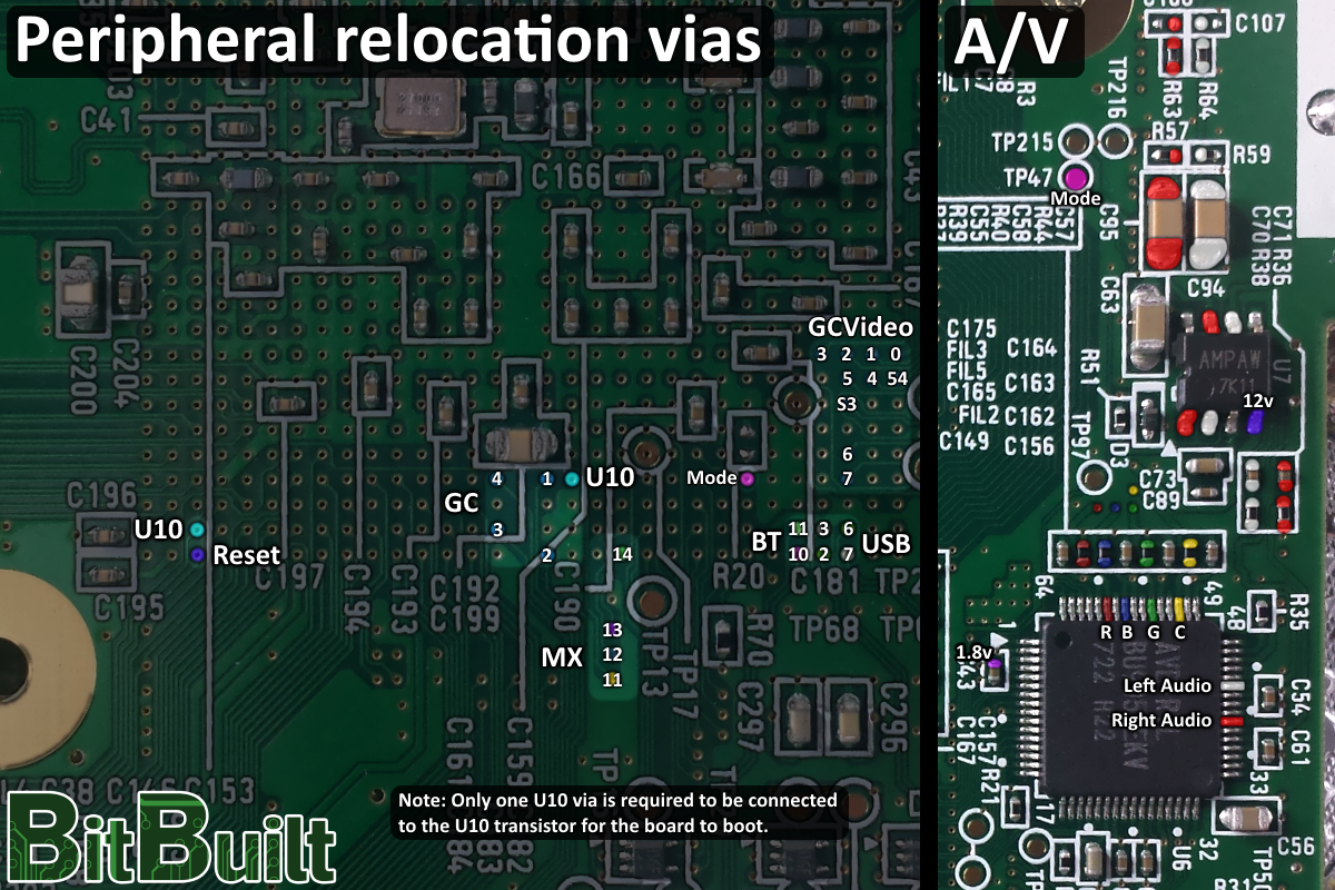
yeah but if i test it against ground it has continuety as i have made the cut little bit bigger(means in safe way like ouside of the bounds)If the board is trimmed, then you don't need to worry about cutting the U10 trace
Scratch the pads a bit with a sharp razor blade to expose as much of the copper as you can, use hella flux, and take your time.yeah but if i test it against ground it has continuety as i have made the cut little bit bigger(means in safe way like ouside of the bounds)
PS: Do you have any tips about soldering that tiny wire to these tiny pads on bottom of gpu/cpu?
Yeah i seem to succesfully soldered 1st wire but as before Is it normal that old u10 pin is connected to ground?Scratch the pads a bit with a sharp razor blade to expose as much of the copper as you can, use hella flux, and take your time.
I tried sanding even more and if i buzz bridged pins of u10 against ground i get beep = they are connected. Should this happen or no? Do you have any available rvl001 board scans(internal layers)?The trace is in an internal layer. When you trim the board you also cut the trace.
The trick to troubleshooting is eliminating as many variables when you test. So wire reset to ground so it will boot into priiloader (this eliminates USB troubleshooting). Make sure the TV shares a common ground with the Wii or it will not work. Also pictures will help us too.Ok after a lot of soldering done i pluged av into tv and mb, power into wall and regulators everything seems fine all voltages are at right levels even through i thought i bridged 2 wires its ok after probing with multimeter U10(U9 in my case when desoldering i lost U10) is getting 3.3v at output leg signals are going from AVE to end of AV cable i know TV works bcz of another Wii, cpu and gpu are slowly heating up(normally) but the MB WONT OUTPUT ANY VIDEO(and/or sound)("no signal" on TV) WTF
Anyone can help?
I used original cable and connector on MB was left as is,The trick to troubleshooting is eliminating as many variables when you test. So wire reset to ground so it will boot into priiloader (this eliminates USB troubleshooting). Make sure the TV shares a common ground with the Wii or it will not work. Also pictures will help us too.
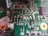
I know that was when I thought it will go smooth i have heatsink ready for itIt appears like you only have thermal pads on the Wii, that is not going to do any good cooling it. You need a heatsink on it. It might make it easier if you unsolder the BT module until you get the wii booting.