
thedrew
.
- Joined
- Sep 27, 2016
- Messages
- 414
- Likes
- 895
After finishing the PS2P, the case felt pretty comfortable compared to all the other small portables I have built. I decided to use the same case and modify the internals for a Wii instead. I am calling this the Wii-C (C standing for Comfort).
The goal of this portable was to not go all crazy with custom boards and whatnot, even though I have a few custom boards made for this portable, but to use parts that I've had laying around.
Specs as of now:
- 5" 640x480 LCD via VGA
- 10,000 mah lipos
- PMS V1 with 9V PD Trigger
- Bluetooth Audio
- Dual Z Buttons
- Dual rumble motors
- 3D printed case
- Removeable Micro SD Card
- OMEGA like trim
- Relocated AVE via Custom Board
- GC+ 2.0
- Large copper heatsink
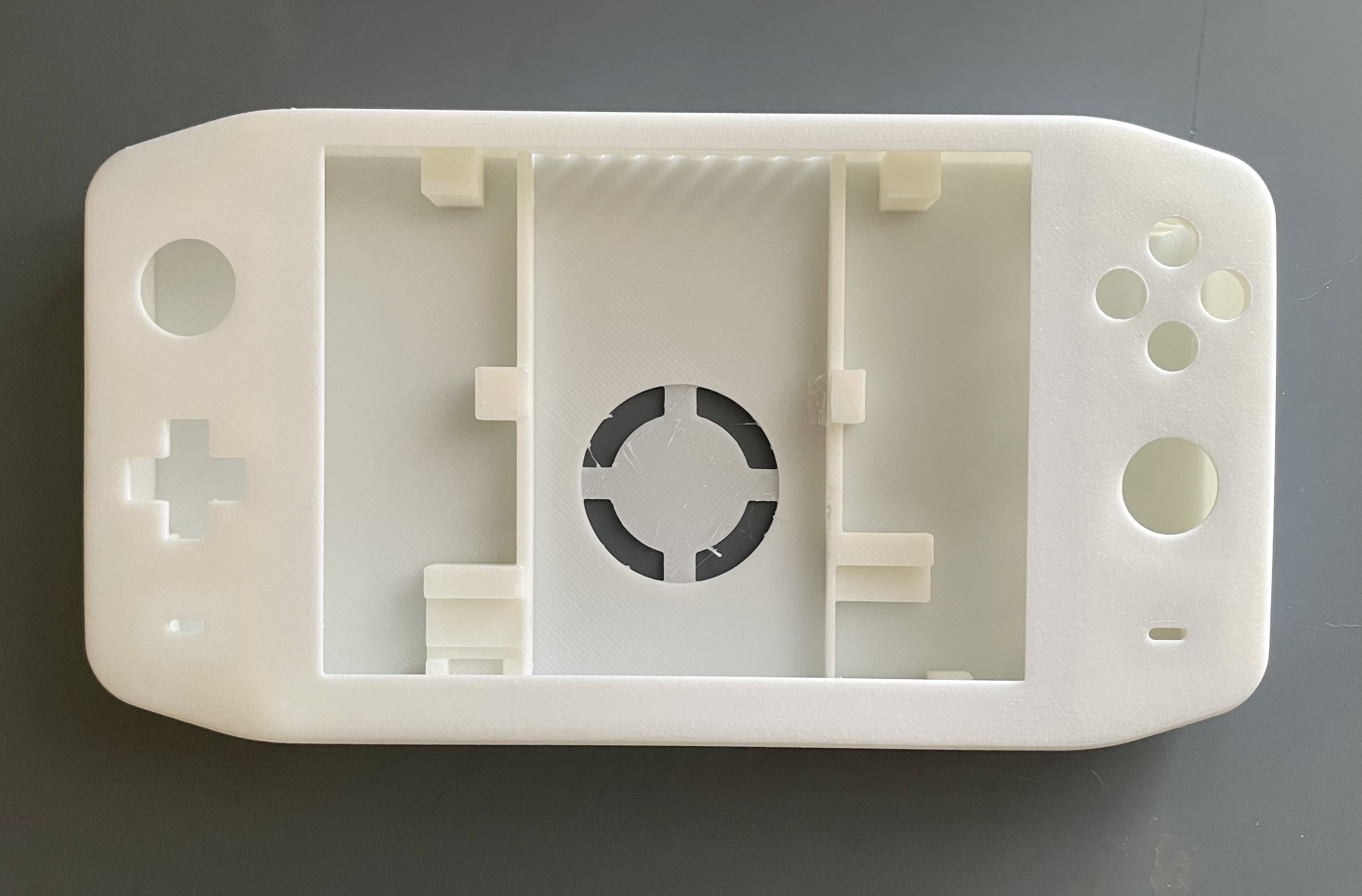
Case test print as of now however I think I will change from DS Lite buttons to the usual Gamecube Style layout since I'm used to that.
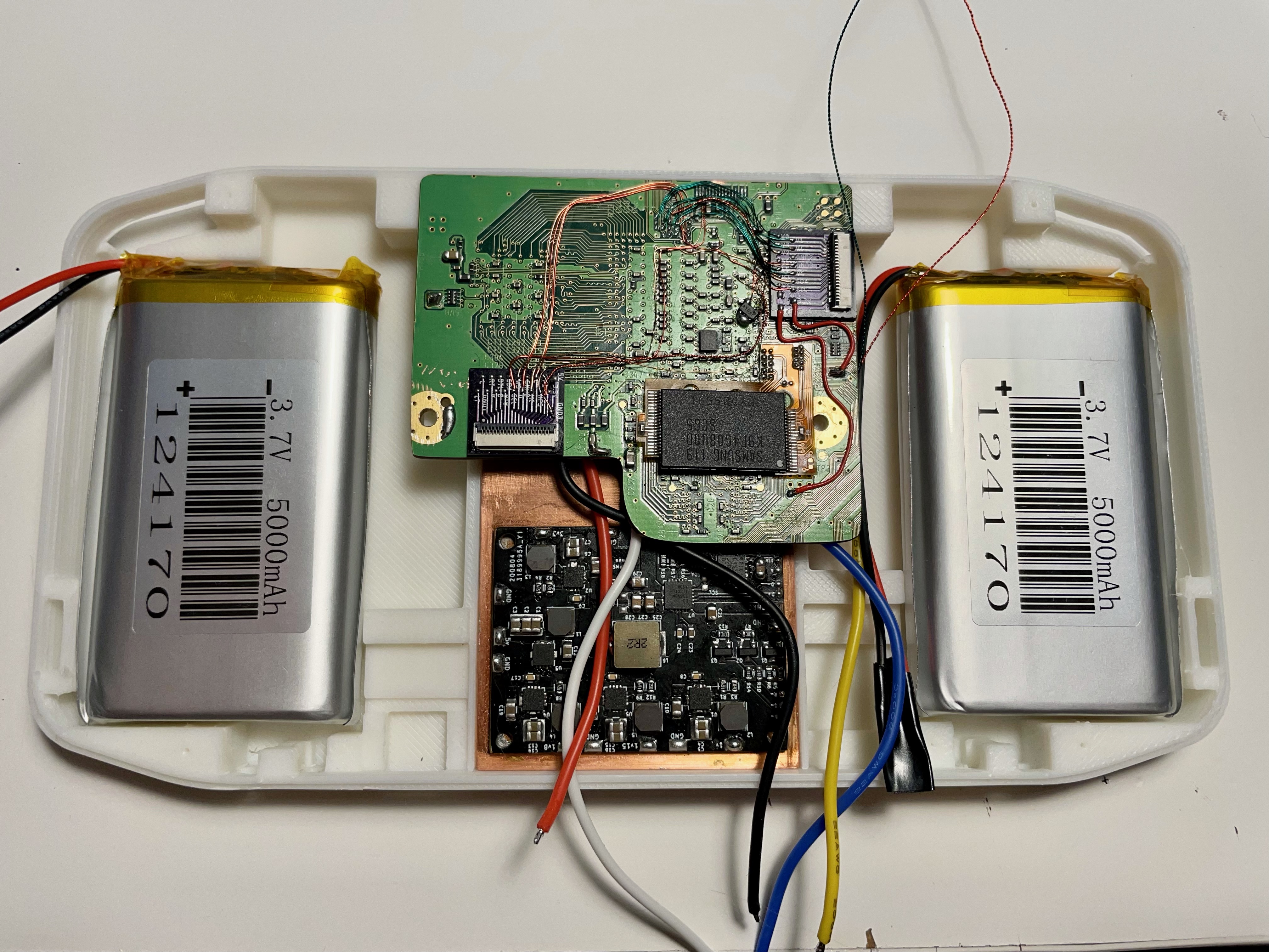
Another goal of this portable is to keep the system a cool as possible. I don't like having sweaty hands and just want peace of mind (since there are lipos inside after all). Since the case has plenty of room, I utilized as much space as possible for a fat copper heatsink. Heatsink dimensions are 48mm x 89mm x 5.6mm.
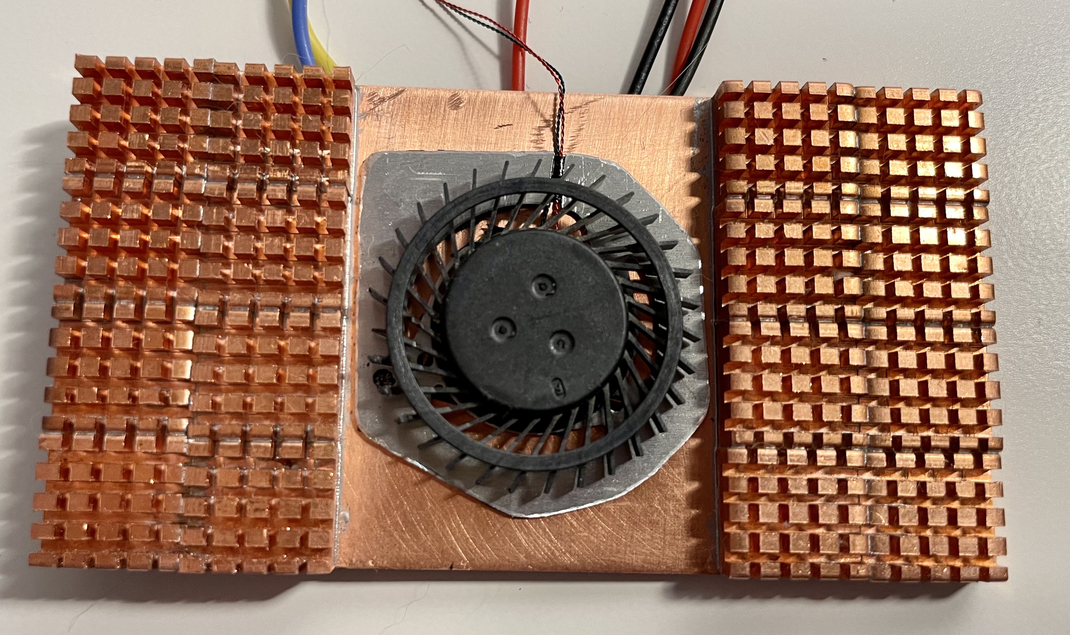
I welded the copper heatsinks on a copper plate via solder paste and hot air which I do for all my portables now. It's a bit heavy to be honest but should stay pretty cool. The blower fan in the middle will blow air through both sides as I will have fan exhaust holes on the bottom and top of the case.
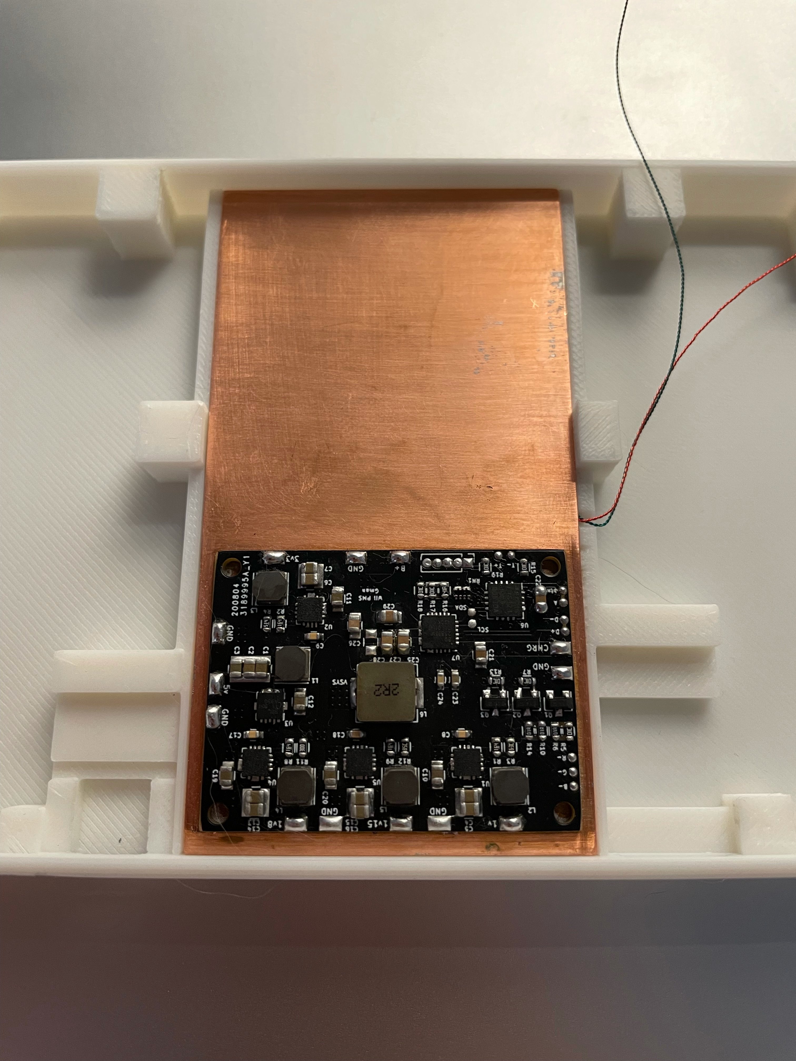
Another reason for the large heatsink is so I can also weld the PMS to it as well. I scratched off the silkscreen on the bottom to expose the ground layer of copper on the PMS and welded that via solder paste to the heatsink as well. Verified it still works as well. This benefited with cooling but also saves space since I don't have screw posts for the PMS on the left or right side of the case allowing for bigger batteries and a thinner portable.
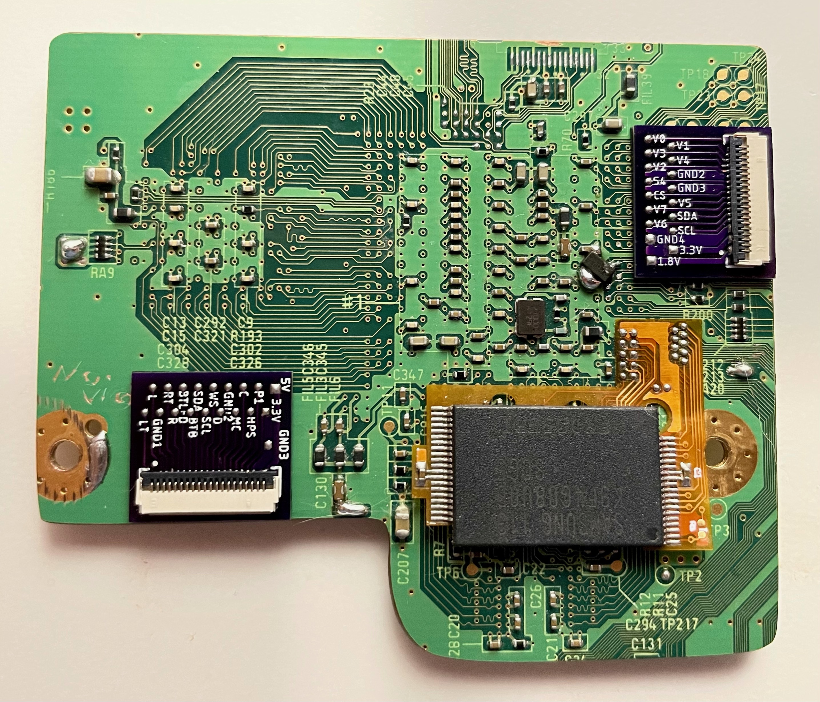
I wanted to use VGA but this trim cuts off the AVE. I used the AVE flex by @YveltalGriffin during testing and worked great but since it's right under the hottest chip on the motherboard, the CPU, I found that little AVE gets too hot for my comfort. I wanted to route the AVE away from the heat, so I created a custom board to help dissipate the heat and so I can use an FFC cable to connect it for cleaner wiring.
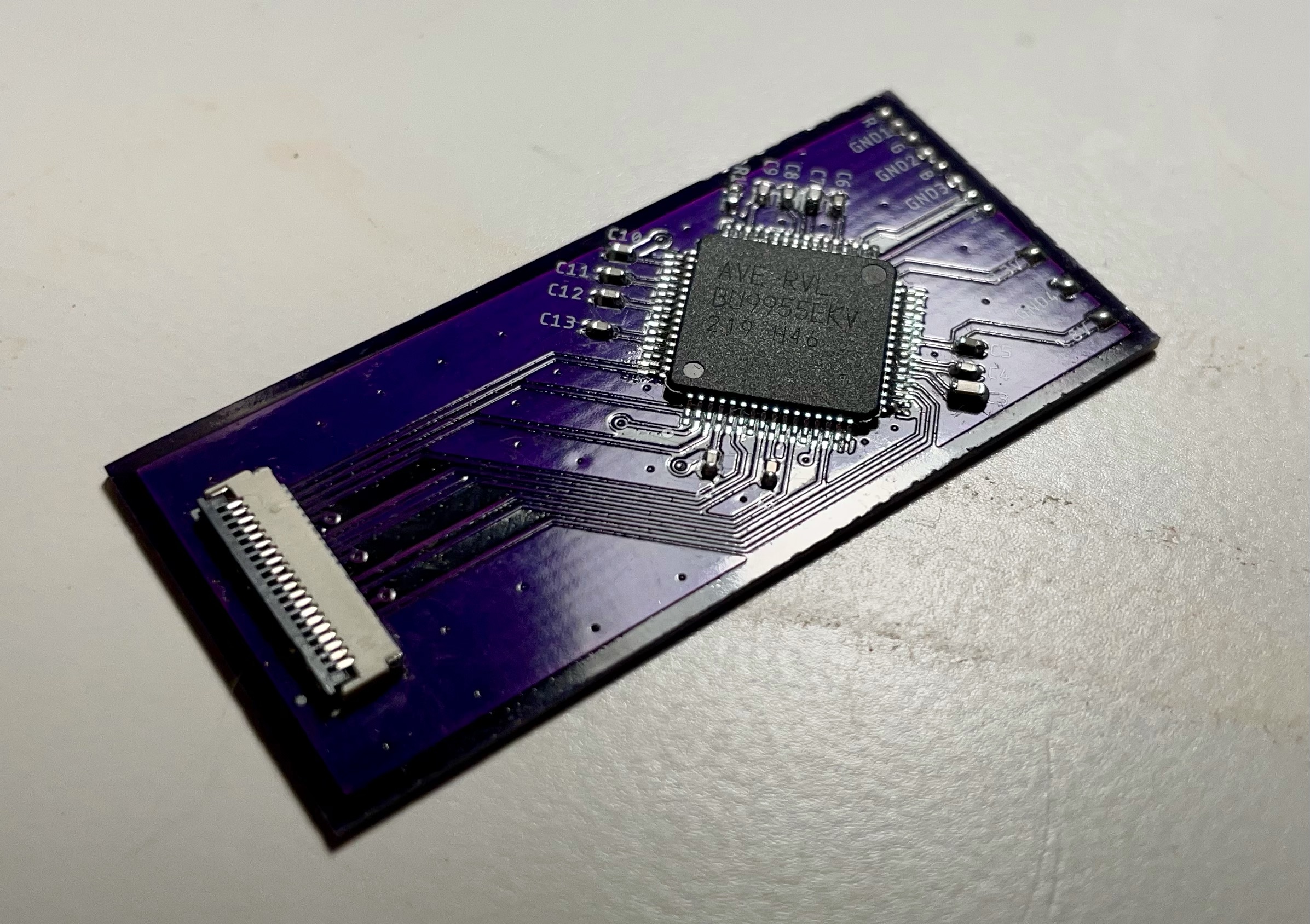
There are 2 FFC breakout boards: 1 for the AVE and the other for various connections so be able to detach/attach both halves of the portable soley on FFC cables.
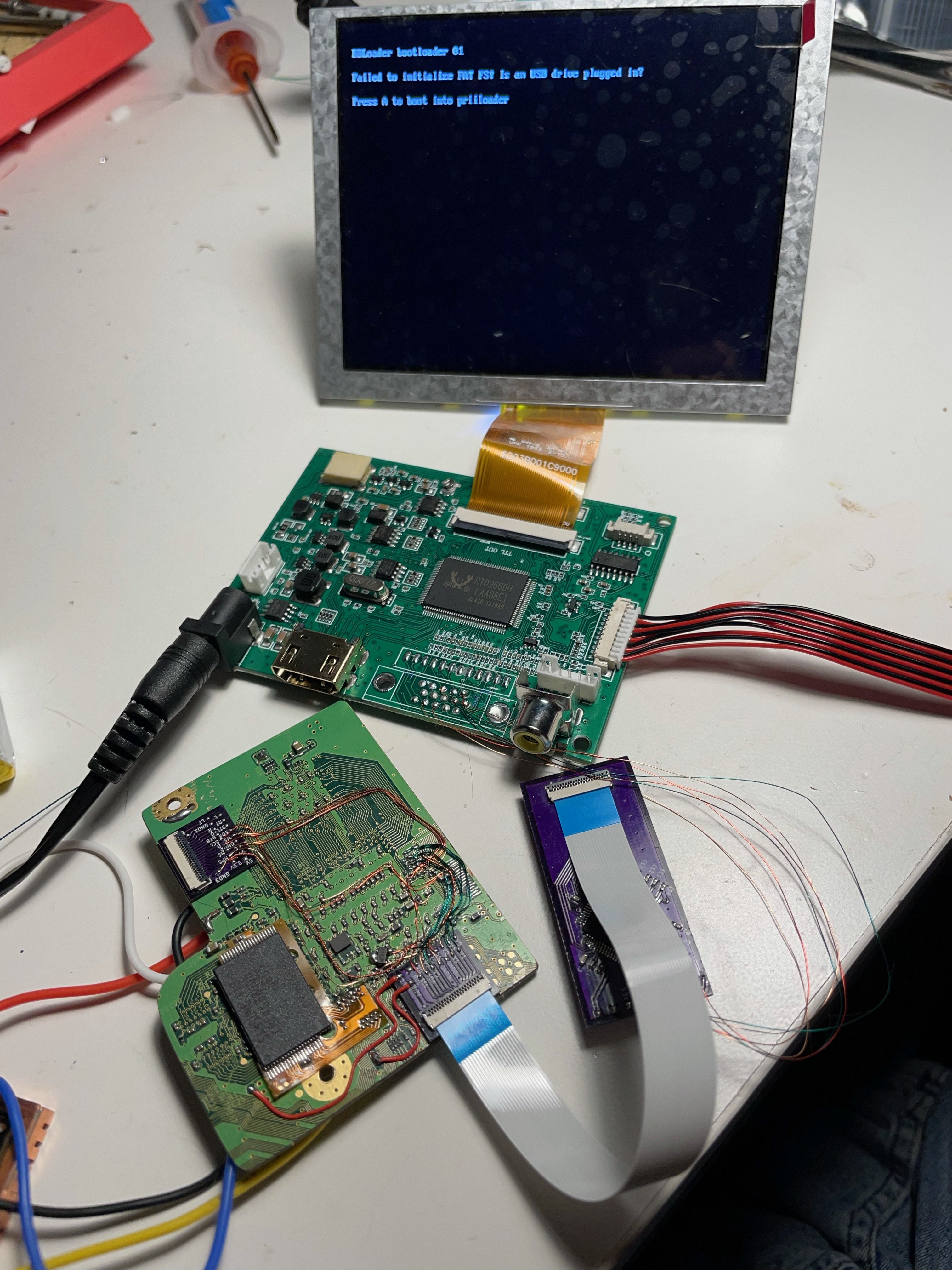
Please excuse the mess, was one of those late modding nights...
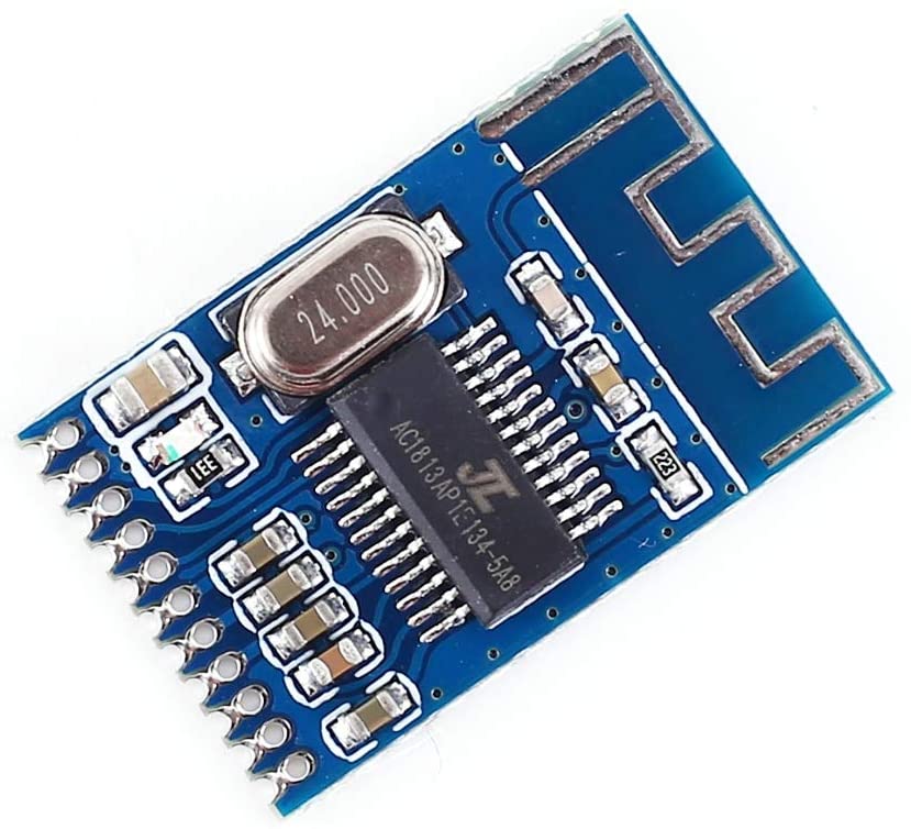
I have done a lot of bluetooth testing and can conclude that this board is the best. Reason being is the audio transmitted is clean compared to the other one in this test. This board version is 1.2 (which is silkscreened on the back).
The bluetooth board I don't advise you to get is this one. It's a newer chip, but has a static buzz that doesn't seem to go away and is distracting. I have tested all 5 that I ordered with the same results with these. This board version is 1.4 (also silkscreened on the back).
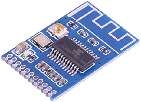
Both bluetooth boards require an antenna installed via the little antenna plug near the crystal, (which can be conveniently taken from the Wii's Wifi) otherwise you'll have choppy audio since the built in antenna is not very strong.
Anyway, everything seems to fit pretty nicely, just have to adjust a few things and maybe create 1 or 2 more custom boards for a couple extra features.
It's pretty closed to finished, but that's all for now.
The goal of this portable was to not go all crazy with custom boards and whatnot, even though I have a few custom boards made for this portable, but to use parts that I've had laying around.
Specs as of now:
- 5" 640x480 LCD via VGA
- 10,000 mah lipos
- PMS V1 with 9V PD Trigger
- Bluetooth Audio
- Dual Z Buttons
- Dual rumble motors
- 3D printed case
- Removeable Micro SD Card
- OMEGA like trim
- Relocated AVE via Custom Board
- GC+ 2.0
- Large copper heatsink
Case test print as of now however I think I will change from DS Lite buttons to the usual Gamecube Style layout since I'm used to that.
Another goal of this portable is to keep the system a cool as possible. I don't like having sweaty hands and just want peace of mind (since there are lipos inside after all). Since the case has plenty of room, I utilized as much space as possible for a fat copper heatsink. Heatsink dimensions are 48mm x 89mm x 5.6mm.
I welded the copper heatsinks on a copper plate via solder paste and hot air which I do for all my portables now. It's a bit heavy to be honest but should stay pretty cool. The blower fan in the middle will blow air through both sides as I will have fan exhaust holes on the bottom and top of the case.
Another reason for the large heatsink is so I can also weld the PMS to it as well. I scratched off the silkscreen on the bottom to expose the ground layer of copper on the PMS and welded that via solder paste to the heatsink as well. Verified it still works as well. This benefited with cooling but also saves space since I don't have screw posts for the PMS on the left or right side of the case allowing for bigger batteries and a thinner portable.
I wanted to use VGA but this trim cuts off the AVE. I used the AVE flex by @YveltalGriffin during testing and worked great but since it's right under the hottest chip on the motherboard, the CPU, I found that little AVE gets too hot for my comfort. I wanted to route the AVE away from the heat, so I created a custom board to help dissipate the heat and so I can use an FFC cable to connect it for cleaner wiring.
There are 2 FFC breakout boards: 1 for the AVE and the other for various connections so be able to detach/attach both halves of the portable soley on FFC cables.
Please excuse the mess, was one of those late modding nights...
I have done a lot of bluetooth testing and can conclude that this board is the best. Reason being is the audio transmitted is clean compared to the other one in this test. This board version is 1.2 (which is silkscreened on the back).
The bluetooth board I don't advise you to get is this one. It's a newer chip, but has a static buzz that doesn't seem to go away and is distracting. I have tested all 5 that I ordered with the same results with these. This board version is 1.4 (also silkscreened on the back).
Both bluetooth boards require an antenna installed via the little antenna plug near the crystal, (which can be conveniently taken from the Wii's Wifi) otherwise you'll have choppy audio since the built in antenna is not very strong.
Anyway, everything seems to fit pretty nicely, just have to adjust a few things and maybe create 1 or 2 more custom boards for a couple extra features.
It's pretty closed to finished, but that's all for now.
Last edited: