Hello Bitbuilt! I finally got around to learning how to model after finishing my G-Wii clone.
In my time on this website, I've seen people make some incredible builds. Wiis that fit in your pocket, portable kits you can buy and build yourself, so on and so forth. But the one thing that seems to be an afterthought is comfort and how a controller feels in your hands.
Introducing the Steamii.
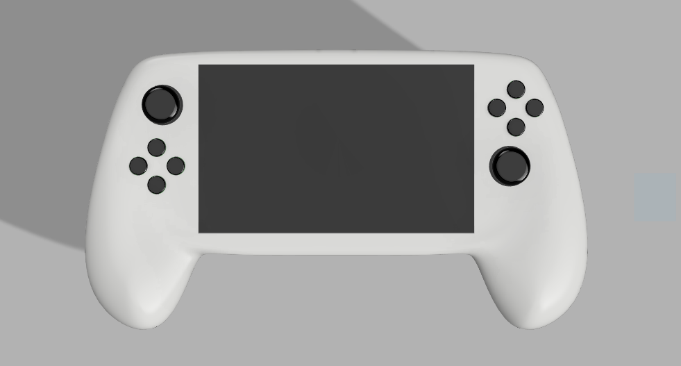
I've always liked the shape of the steam controller but never found it comfortable to use because of how you have to angle your thumbs and drag them against pads. This is my chance to not only make a comfortable portable using a shape no one has used yet but correct features I personally think held back the steam controller.
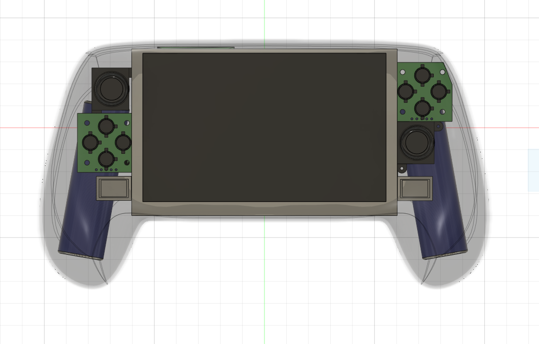
Every part you see except for Wesk's models was modeled by me. It was a pain to try and convert/modify the actual steam controller case from the ungodly amount of polygons it has so I just used the model as a guide for the create form tool in fusion 360. Was it the easiest or fastest way of doing it? No. But it was the easiest for me to do since I have no experience with fusion.
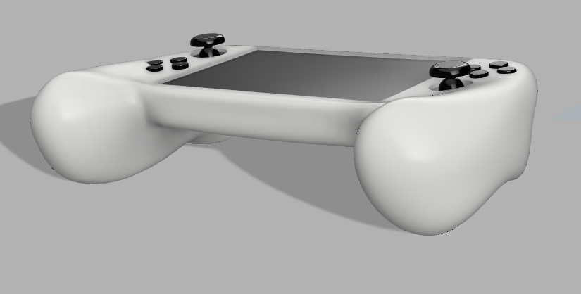
There are a couple of things missing from the current render like holes for the speakers, cutting the case in half, shoulder buttons, mounting, etc. but you get the basic idea.
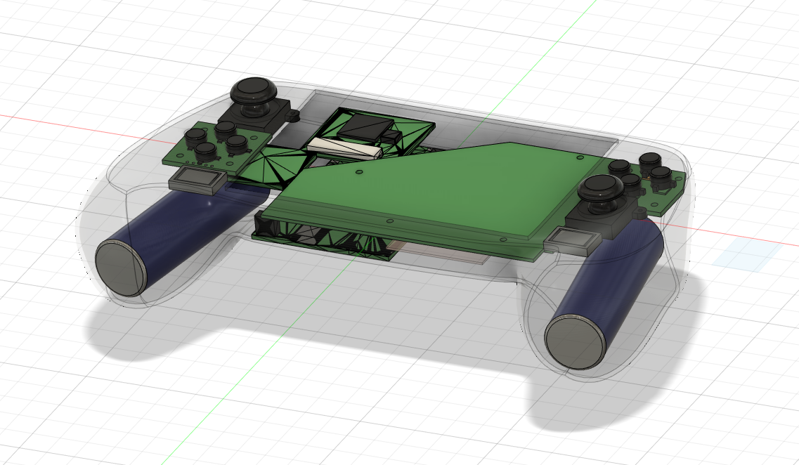
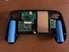
The Steamii will have an RVL-PMS, USB-C, GC+2.0, U-AMP modified for WiiHUD, 2 Switch breakout boards, RVL LCD Double Dong on a 4.3" screen, 2 joycon sticks, 2 700mw SP-1511-3 speakers, 2 5v ERM motors, 2 Samsung 50E 21700 4900mAH batteries, and 2 dual-action tactile buttons because I don't want to do the "glue-two-buttons-together" method again.
Eventually, I'd like to add a custom PCB of some sort to make the console beep when you turn it on like an actual steam controller.
In my time on this website, I've seen people make some incredible builds. Wiis that fit in your pocket, portable kits you can buy and build yourself, so on and so forth. But the one thing that seems to be an afterthought is comfort and how a controller feels in your hands.
Introducing the Steamii.
I've always liked the shape of the steam controller but never found it comfortable to use because of how you have to angle your thumbs and drag them against pads. This is my chance to not only make a comfortable portable using a shape no one has used yet but correct features I personally think held back the steam controller.
Every part you see except for Wesk's models was modeled by me. It was a pain to try and convert/modify the actual steam controller case from the ungodly amount of polygons it has so I just used the model as a guide for the create form tool in fusion 360. Was it the easiest or fastest way of doing it? No. But it was the easiest for me to do since I have no experience with fusion.
There are a couple of things missing from the current render like holes for the speakers, cutting the case in half, shoulder buttons, mounting, etc. but you get the basic idea.
The Steamii will have an RVL-PMS, USB-C, GC+2.0, U-AMP modified for WiiHUD, 2 Switch breakout boards, RVL LCD Double Dong on a 4.3" screen, 2 joycon sticks, 2 700mw SP-1511-3 speakers, 2 5v ERM motors, 2 Samsung 50E 21700 4900mAH batteries, and 2 dual-action tactile buttons because I don't want to do the "glue-two-buttons-together" method again.
Eventually, I'd like to add a custom PCB of some sort to make the console beep when you turn it on like an actual steam controller.