Hi guys, I have begun a PS2 project recently and am getting the hand of things, though there is plenty of things I am clueless about and need some help!
I am a complete electronics noob, and somewhat a novice in 3D modelling, just FYI.
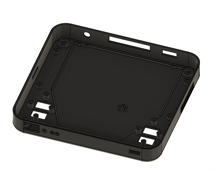
I have modelled my own case, which is now in the 3D printed testing stage to iron out any tolorance issues.
Here is a run down of what I have done so far and what needs doing:
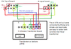
The screen size will vary, as I am struggling to find a screen that has a drive board that is well documented and can be ran off 5V, if anyone can help me out with this I would be greatful!
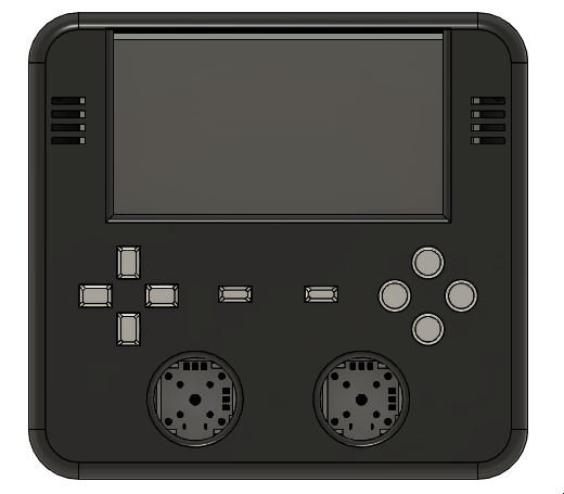
Buttons are all custom, only using the OEM Analog sticks on a custom made bracket.
Buttons have not been tested, and have little experience with modelling buttons so more advice would be great!
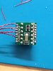
Tactile switches will be mounted to plastic mounts, however I have reconsidered this and may end up using perfboard/custom PCBs as a more secure mount.
The back section has rough cutouts for various ports, am considering having the memory card internal as well as the USB, if I can justify the space. Case is currently 40mm or so thick, but considering the awkwardly placed rear buttons I think it works in my favour.
I have another rough cutout for the MB, but have yet to cut the pcb down and see if it fits.
I have also included vents for better airflow, should i choose to use a blowerfan.
")
I am a complete electronics noob, and somewhat a novice in 3D modelling, just FYI.
I have modelled my own case, which is now in the 3D printed testing stage to iron out any tolorance issues.
Here is a run down of what I have done so far and what needs doing:
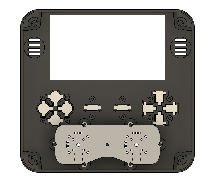
Front
The screen size will vary, as I am struggling to find a screen that has a drive board that is well documented and can be ran off 5V, if anyone can help me out with this I would be greatful!
Front Internals
Buttons are all custom, only using the OEM Analog sticks on a custom made bracket.
Buttons have not been tested, and have little experience with modelling buttons so more advice would be great!
Tactile switches will be mounted to plastic mounts, however I have reconsidered this and may end up using perfboard/custom PCBs as a more secure mount.
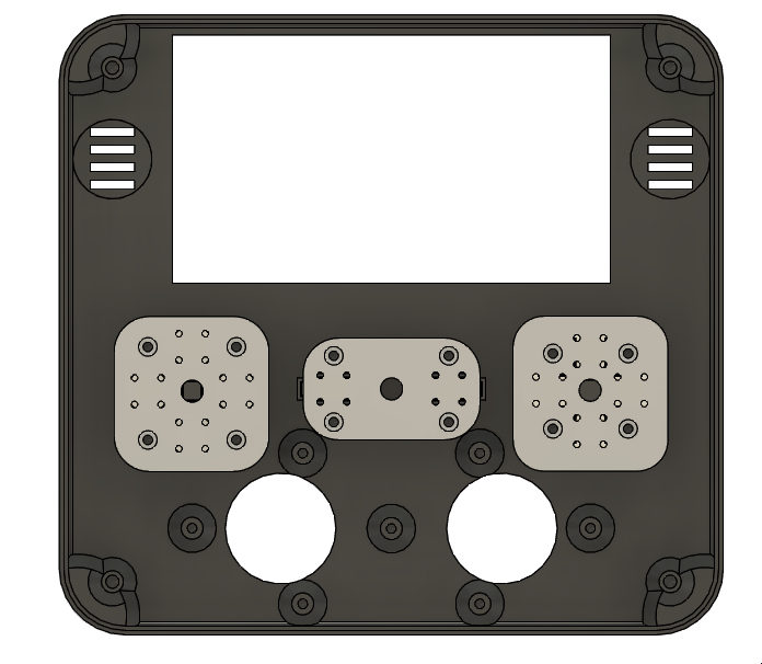
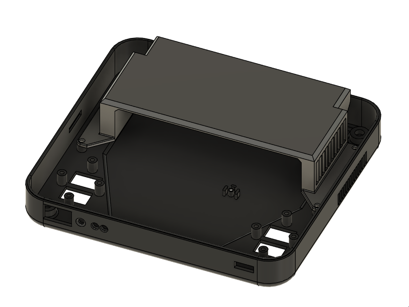
Back Internals
The back section has rough cutouts for various ports, am considering having the memory card internal as well as the USB, if I can justify the space. Case is currently 40mm or so thick, but considering the awkwardly placed rear buttons I think it works in my favour.
I have another rough cutout for the MB, but have yet to cut the pcb down and see if it fits.
Bracket
I'd say this is my magnum opus, since it will use up a lot of dead space in the case. Hoping to mount things like the batteries, charge board, amp board and even the controller pcb to this.
I have also included vents for better airflow, should i choose to use a blowerfan.
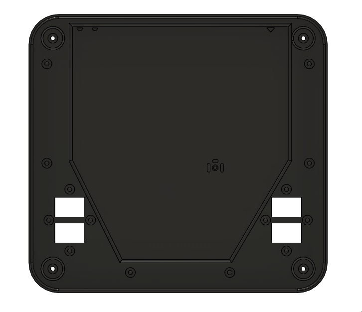
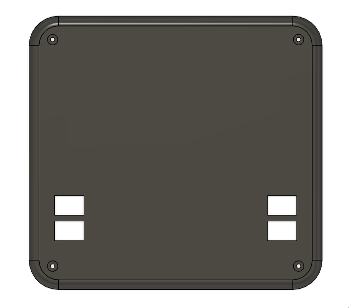
Back
Nothing too fancy here, might slap a logo on it once I decide on a name for this baby
Things I haven't done yet
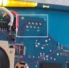
- Test my PS2 motherboard.
- Trim the board if it works (Standard Trim).
- Wire everything up without screwing it up (Unlikely, lol).
- Create test prints, mainly for buttons and tollerance checks. (And show them, of course!)
- Profit.
Last edited: