
cy
.
- Joined
- Sep 3, 2020
- Messages
- 116
- Likes
- 325
- Portables
- 6
Due to interference and panel issues I've had to replace the screen in my G-Wii. Luckily I happened to have another 5 inch screen on me, but I'm having trouble modding it for 5 volts. It appears to be an alternative model of the ZJ050NA 08C screen as that is the screen I ordered but the driver board I was sent looks like this.
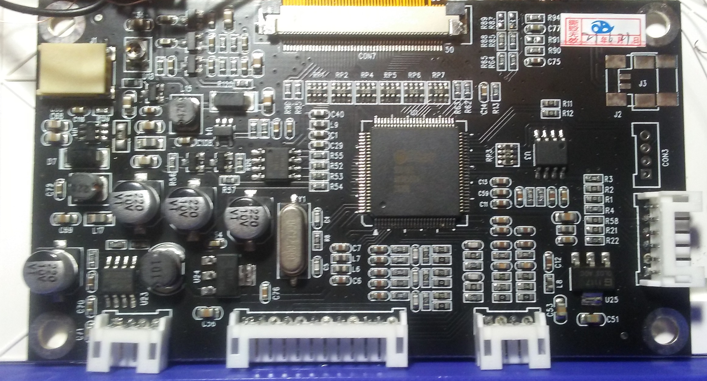
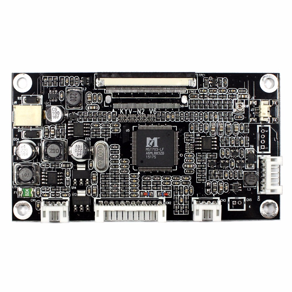
At a glance it appears to be the same driver board. But if you look closely you'll see it absolutely isn't. Here's what the driver board should look like for reference:
I attempted to google the voltage regulators and I've not had any luck finding any info on them. Here's what the regs say:
The reg right by the 12 volt reads(it's the chip in the bottom left corner)
MP 14820NF5804507MPSF34
There's a reg that looks similar to it on the right nearish to the top that reads
ATM HK 21824C16N SU27H
The reg to the right of that chip I mentioned earlier reads
1117 0P 1G 33C
Finally, the reg on the bottom right reads
1117 0L03 A0C
It might also be worth mentioning the big chip in the center of the screen appears to be completely different. Here's what that says:
Star(seems to be the brand name)
SSD 102AW005D7A2033R
I was attempting to follow this guide, but yeah, haven't been able to find the data sheets for these regs.