Question Questions during my Boogii Ashida build

Joined
Jun 12, 2022
Messages
4
Likes
2
Instead of making lots of threads for my questions, I am going to ask them all here. Hopefully that is alright. Here was my first question about z button switches.

Hey all, started putting together my own ashida today. The picture enclosed shows the ashida controller pcb, an extra switch i ordered that is the same as the power button, the two z button switches I sourced from the BOM, and a third-party gamecube controller pcb I figured I would open up to salvages parts if i needed them. A broken, original gamecube controller is coming in the mail that I will harvest most controller pieces from.
20220730_150820.jpg

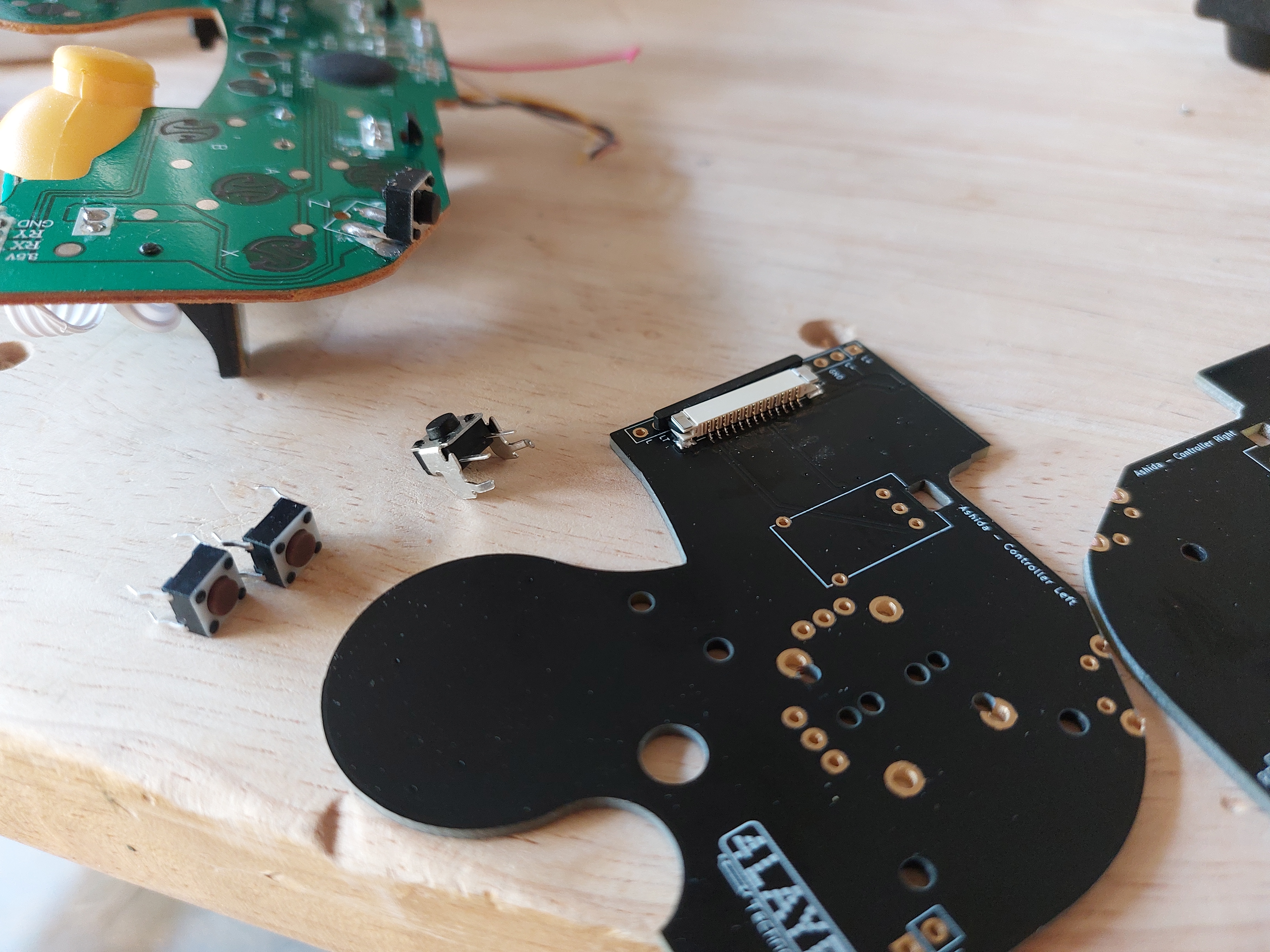
So I am thinking that the BOM might be wrong about these digikey switches I ordered? They are not right angle mount switches to my knowledge. I do like their feel however.

The extra power switch I ordered is a right angle mount, but actually faces the wrong way (inside the controller) instead of out to where the z button will be placed.

Obviously I don't really want to harvest that dingy z switch from the third party controller, especially since it only has 2 solder points.

Assuming the original controller has the switch I need, I would still require an additional switch for the other z button. Any advice for making one of these switches here work, or a link to buy a proper replacement?
 
Last edited:
Joined
Jun 12, 2022
Messages
4
Likes
2
Thanks Wesk. I'll wait to see how the original switch feels but I will definitely use at least one of those ones I ordered from the Ashida BOM.

Trimmed my Wii today! Here are some pictures. I was referencing the trimming guide on the g-boy assembly manual for the lines on the board. I hope I didn't brick this one. I also trimmed out the MX chip.
20220731_163557.jpg

20220731_163605.jpg
You'll notice that one of the large components on the diagonal trim line had a hard time coming off. Should I be worried about that?

I am really hoping I am not going to short something, so I have checked the resistances on the board.
Here they are. Some of them seem really off compared to the resistances I have seen on Nold's thread. Am I screwed?
20220731_163858.jpg
Perhaps my odd resistances are from not trimming down enough?
Thanks for any and all help, you guys.
 
Joined
Jun 12, 2022
Messages
4
Likes
2
Hey all!
I have ran into issues with my ashida case that I ordered from PCBway (it became warped from heat and pressure from sitting the my car's trunk, which would be my fault), and it ended up breaking. Lots of super glue and bondo were no match for the thin part of the case, close to where the usb C port is, and it broke off again while I was sanding it down. I am reprinting with my own 3D printer now, hoping that one will turn out better. The top part of the case is still intact and I have begun placing the screen and buttons into that section. I decided I would test my wii and wire most everything inside of my broken bottom half of the case, and then transfer everything to the new one I have printing right now once it is ready.

In the meantime, I have been slowly soldering components together to try and test the wii. I just need a bit of additional help with some things.
First, are there any resources such as pinouts for the VGA on the drive board I bought from 4Layertech? I know how to solder to the wii but not how to solder to the drive board. I will probably test the wii with composite but I imagine VGA will be a must later on.

Second, I am a little confused about the whole RVL-PMS lite and its lack of the 1.8v regulator. Any components that require 1.8v can be connected to the rail on the wii motherboard, which just has the LDO which consumes more power?
 

Stitches

2 and a Half Dollarydoos
Staff member
.
.
Joined
Feb 5, 2017
Messages
3,817
Likes
3,010
Location
Banana Bender Land, Australia
Portables
6
Hey all!
I have ran into issues with my ashida case that I ordered from PCBway (it became warped from heat and pressure from sitting the my car's trunk, which would be my fault), and it ended up breaking. Lots of super glue and bondo were no match for the thin part of the case, close to where the usb C port is, and it broke off again while I was sanding it down. I am reprinting with my own 3D printer now, hoping that one will turn out better. The top part of the case is still intact and I have begun placing the screen and buttons into that section. I decided I would test my wii and wire most everything inside of my broken bottom half of the case, and then transfer everything to the new one I have printing right now once it is ready.

In the meantime, I have been slowly soldering components together to try and test the wii. I just need a bit of additional help with some things.
First, are there any resources such as pinouts for the VGA on the drive board I bought from 4Layertech? I know how to solder to the wii but not how to solder to the drive board. I will probably test the wii with composite but I imagine VGA will be a must later on.

Second, I am a little confused about the whole RVL-PMS lite and its lack of the 1.8v regulator. Any components that require 1.8v can be connected to the rail on the wii motherboard, which just has the LDO which consumes more power?
The pinout should be written in white silkscreen on the underside of the driver board.

And yeah, anything that needs 1.8v including the PMS lite itself can grab power directy from the Wii's 1.8v LDO
 
Top