Worklog PS2 portable (not named yet)

Joined
Jul 7, 2017
Messages
46
Likes
39
Location
Spain
Hi, I'm planning on building a PS2 portable out of (mostly) recycled parts the updates of the worklog will be once a week or once every two weeks since I don't have much time.
I have in mind this:
-10.1" screen from an old tablet (16:10 ratio and 1280x800 resolution).
-Batteries resourced from laptops battery packs.
-Charge/protection circuit from a 7.4v DVD battery pack.
-Knockoff controller.
-Small speakers (from the same tablet).
-Expansion port, so I con connect it to a dock and then have 2 players input and TV out (maybe an IDE cable+connector).
-Case made out of wood.
-Laptop fan (more efficient and quieter than the stock one).
-PS2 SCPH-77004 motherboard.
It will be a small laptop like portable. I got inspired by @Madmorda ´s Wii S Lite.
 
Joined
Mar 18, 2017
Messages
281
Likes
135
Location
The Mitten
Ooh. Clamshell. Good luck. I hear those things are almost impossible. There is a reason we all make landscape style portables. They are a lot easier.

Also, trying to use recycled screens can be super hard. Unless you can find a driver board for that exact screen, it will be almost impossible to put your signal into the screen.

But i wish you luck as you start your journey.
 
Joined
Apr 1, 2017
Messages
162
Likes
119
Location
UK
Portables
0
What type of connector does the screen have? I was tempted by a few 10" TTL screens but figured it'd drain battery like a monster
 
Joined
Jul 7, 2017
Messages
46
Likes
39
Location
Spain
Also, trying to use recycled screens can be super hard. Unless you can find a driver board for that exact screen, it will be almost impossible to put your signal into the screen.

But i wish you luck as you start your journey.
Well, I already have a programmable driver board (with the .bin file) and the propper cable. Thanks

What type of connector does the screen have? I was tempted by a few 10" TTL screens but figured it'd drain battery like a monster
It uses a LVDS interface and according to the datasheet it draws around 3,6W (max) with a white pattern
 
Joined
Jul 7, 2017
Messages
46
Likes
39
Location
Spain
Small update:
-I´ve measured all of the PCBs and batteries
-Tested power draw of the screen (12V@380mA = 4,56W)
-I saw that the metal housing of the ps2 is rusting a bit, I know that I can get rid of the rust by sandind it, but then it will rust again in 2 days probably, any protective coating that I can use?
-I´m starting to draw 3D models of everything to see what´s the best way to distribute all the components
 

BocuD

.
Joined
Jul 21, 2016
Messages
468
Likes
606
Location
The Netherlands
Portables
3
Small update:
-I´ve measured all of the PCBs and batteries
-Tested power draw of the screen (12V@380mA = 4,56W)
-I saw that the metal housing of the ps2 is rusting a bit, I know that I can get rid of the rust by sandind it, but then it will rust again in 2 days probably, any protective coating that I can use?
-I´m starting to draw 3D models of everything to see what´s the best way to distribute all the components
What are you using to get 12v to the display? Also, what do you mean with rust? pics please. Your project looks good to me, but if you want to use a clamshell design I wish you a lot of luck with it since its really hard.
 
Joined
Jul 7, 2017
Messages
46
Likes
39
Location
Spain
Well @BocuD the driver board (and the screen) can be powered all the way down to 6V so thats not an issue (also, I´m looking the power circuitry to see if I can bypass a regulator to make it work with even less voltage)
And with rust I mean that it looks like this
IMG_20171114_143620.jpg


Also, I have some ideas on how to make the clamshell desing work, I asume that I will need to do trial and error
 

BocuD

.
Joined
Jul 21, 2016
Messages
468
Likes
606
Location
The Netherlands
Portables
3
If I was you I would just ditch the shielding overall. It's not like you're going to need it in a portable. Also, did you look into custom regulators for your PS2? And do you have plans to trim it? Custom regs could reduce power consumption by a lot. I'm not sure if the PS2 uses switching or linear regs but if they are linear you should look into replacing them with custom ones. Also, can you send a picture of your screen driver board? Maybe I can help looking for the regs you want to bypass.
 
Joined
Jul 7, 2017
Messages
46
Likes
39
Location
Spain
I can't take a picture of it atm but it is exactly the same as this one

ps12331319-v29_lcd_tv_controller_board.jpg
The circle in red indicates where is the first regulator, I will look deeper into it tomorrow and the PS2 onboard regs are mostly the switching type, but @Gman built his last portable with custom regs (increasing efficiency). I considered the idea of using them but for now I will stick to the stock ones (who knows, maybe I'll use them on a second revision, or a second portable, it would be awesome but hard to try to run it from a 1S xP config)
 

BocuD

.
Joined
Jul 21, 2016
Messages
468
Likes
606
Location
The Netherlands
Portables
3
I found the datasheet for your driver board, and it specifies that the voltages for the panel are 3.3v and 5v. You should be able to replace the built in regulators with custom ones if you want, and could probably pull 5v and 3.3v from the ps2. Can you take closer high resolution pictures of these points?
ps12331319-v29_lcd_tv_controller_board.jpg


Also, since the PS2 regs are already switching ones I wouldn't replace them.
 

ahrlad

.
Joined
Oct 29, 2017
Messages
39
Likes
33
Which display interface will you use? The chipset supports ypbpr, but it's usually not programmed correctly.
 
Joined
Mar 18, 2017
Messages
281
Likes
135
Location
The Mitten
We had a discussion about this the other day on a different thread. Just because the main ic chip supports y, pb,pr that doesnt mean the driver board and driver software are created to support that video input.
 

ahrlad

.
Joined
Oct 29, 2017
Messages
39
Likes
33
Yeah, that's why I asked ;)

I've seen a couple of boards with this chipset that do have a dedicated ypbpr header or RCA jacks, but maybe you can fool it into accepting RGB as well?

It would be sad to have to settle for composite input when the LCD and controller can do so much better.
 
Joined
Jul 7, 2017
Messages
46
Likes
39
Location
Spain
Can you take closer high resolution pictures of these points?View attachment 4431
First circle: it is a ZTP7193SI step down switching regulator
Second one: it is a 1084 LDO regulator (3.3V) (according to TI datasheet it is 5A capable, overkill considering that it is after the 3A ZTP reg)
Third: it is a 25L8006E SPI flash
Fourth circle: simple audio amp to drive the speaker
If you want to know, on the right of the LVDS connector and the main IC there is a 1117 regulator (seems like the adjustable version since it has "ADC" written instead of the regular 33C or so indicating it's voltage) and next to the usb there is another 1117 at 3.3V that isn't on the photo (it powers the TV decoder IC so I can remove it to reduce a bit the power draw)

Which display interface will you use? The chipset supports ypbpr, but it's usually not programmed correctly.
I have a V29 IC and looking around the internet the only boards that seems to have YPbPr input are the ones that mounts V59 IC

Maybe I'll try to get the VGA using the H and V sync vias on the motherboard, but I am expecting that the VGA in of the board doesn't support 15kHz
 

ahrlad

.
Joined
Oct 29, 2017
Messages
39
Likes
33
First circle: it is a ZTP7193SI step down switching regulator
I have a V29 IC and looking around the internet the only boards that seems to have YPbPr input are the ones that mounts V59 IC

Maybe I'll try to get the VGA using the H and V sync vias on the motherboard, but I am expecting that the VGA in of the board doesn't support 15kHz
I've seen v29 boards with ypbpr, so I don't think so -- sadly they're not common. From some random datasheet I can't find any other difference than "(V59 for the 3D video decoder, USB function support)": http://www.nodkaindustrial.com/download/ND-JX-V2959.pdf

You're probably correct about the vga sync, though I'd like to hear results if you try it. The board does seem to support 480i over hdmi, so maybe one of those cheap hdmi adapters might work?
 

BocuD

.
Joined
Jul 21, 2016
Messages
468
Likes
606
Location
The Netherlands
Portables
3
If my readings are correct you should be able to connect 3,3v to the pins highlighted red and black to power the board. I wouldn't power it from your ps2 since it (might) require up to 2.5A, but you'd need to measure it. Also, make sure that if you measure the pins that they are a steady 3.3v before trying to power the board. You should be able to trim off the entire section in red, since the only things on there are some ports and audio lines which aren't important, since VGA and composite video aren't trimmed off. Good luck with your portable, it looks great!
 

Attachments

Joined
Apr 1, 2017
Messages
162
Likes
119
Location
UK
Portables
0
If my readings are correct you should be able to connect 3,3v to the pins highlighted red and black to power the board. I wouldn't power it from your ps2 since it (might) require up to 2.5A, but you'd need to measure it. Also, make sure that if you measure the pins that they are a steady 3.3v before trying to power the board. You should be able to trim off the entire section in red, since the only things on there are some ports and audio lines which aren't important, since VGA and composite video aren't trimmed off. Good luck with your portable, it looks great!
If you do trim it, make sure that oscillator isn't required or not trim it off. They're used for clock generation, likely needed for the encoder to function properly.
 

BocuD

.
Joined
Jul 21, 2016
Messages
468
Likes
606
Location
The Netherlands
Portables
3
If you do trim it, make sure that oscillator isn't required or not trim it off. They're used for clock generation, likely needed for the encoder to function properly.
Yeah, thats my mistake. I meant to trim just before but i guess my pdf editor messed up.
 
Joined
Jul 7, 2017
Messages
46
Likes
39
Location
Spain
I've finally made some progress, now I have everything 3D modeled (with exams and holydays with the family I only had time to hand draw all the parts and where they belong to. So I had everything sketched in 2D, now it's 3D :D 
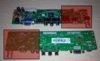
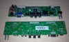
) here are some pictures, I will start building it as soon as I have time, it's going to be slow.

Sin título1.png

Here is the inside of the lower bottom half (it isn't going to have all those batteries, just a few. The vent holes may change a bit).

Sin título3.png

Upper bottom half with the buttons and joysticks (I may move them down 1cm or so to make a little bit of space for the driver board underneath it) external memory card (connected to port 1, in port 2 there is a FMCB memory card) to transfer saves and the hole for the USB that contains all the games.

Sin título2.png

This is the top half with the hinges mounted (there isn't a lot to say, it just holds the screen.

Sin título.png

Detail of the hinges at the top.

Sin título5.png

The hinges will have a rubber ring or something to make friction and keep the screen in the desired position.

Sin título7.png

Hole for the screw that will adjust the hinge tension.

Sin título4.png

Finally a detailed picture of the hinges mounted in the bottom half.
 
Top