Worklog Portable Xbox 360 (slim corona)

Benge

.
Joined
May 18, 2020
Messages
201
Likes
689
Location
France
Portables
4 : O-Wii (V1,V2,V2.1)/ BS2
PCBs are working perfectly !
vlc_olPrCdAcNP.png

vlc_dnSRYWfjkK.jpg

Who wants a slice of 360?
With the new PCBs I can remove this part and it works !
100% on battery so Portable !

Then I analyzed and reconnected all the wires needed to cut out this other part, but after a lot of testing and research no boot.
The southbridge is cold (25°C instead of 50°C on), there is the middle green LED ON but not the LED circle animation of the start.
IMG_2458.JPG


Currently I found the problem ! (I'm not sure why but I think it's very stupid).

Here is the full video :
The French subtitles are corrected so normally the auto translation should work well
(I don't do the English translation because youtube displays it badly and it becomes complicated to read and follow the video).
 
Last edited:

Benge

.
Joined
May 18, 2020
Messages
201
Likes
689
Location
France
Portables
4 : O-Wii (V1,V2,V2.1)/ BS2
Good news the motherboard is not dead !

For booting the 360, a connected HDMI or video cable is needed, but that was not the problem here.
In fact I had just forgotten to color a part which is connected to the 3.3V and which powers the southbridge.
So of course I had forgotten to connect it.
ForgotToColoriaJe.png


After that I installed my PMS properly, and I was able to test that the new LDOs worked well :
IMG_2525.JPG

IMG_2528.JPG

Nand relocation time :
IMG_E2533.JPG


Last Trim and VOILA !
P1050573.JPG

IMG_2548.JPG


The trimmed motherboard could very easily fit into a Wii
another size comparison for fun :
IMG_2557.JPG

What's good is that I know I can still cut a few mm on the top, easily remove 5mm on the RAM side, and a little more on the other side.

Anyway, guys, here is the first trimmed Working Xbox 360 motherboard !!!

If you want more details or see me struggle, here is the full video :
TRADUCTION are not accurate YET, French subtitles aren't corrected yet, in about 6 hours it should be good

 
Joined
Apr 29, 2021
Messages
2
Likes
0
we want xbox 360 portable. desperate for one more video I check every youtube notification to see if it was millomaker who just uploaded a video
 

Nold

real emulation, no hardware
Staff member
.
.
2021 1st Place Winner
Joined
Jul 16, 2017
Messages
443
Likes
1,609
Location
EU
Portables
5 + 1*π
damn how could i totally miss this insane thread O.o...

I just which i could understand your videos :D

1696922713135.png
 

Benge

.
Joined
May 18, 2020
Messages
201
Likes
689
Location
France
Portables
4 : O-Wii (V1,V2,V2.1)/ BS2
damn how could i totally miss this insane thread O.o...

I just which i could understand your videos :D

View attachment 30196
Hey Nold,
Its been a while since the last update ahah
Too much work to add to this, maybe I will add the progress when I have free time after the ending.

I got the reference :XD:
Hope Youtube will add the AI automatic doubling soon :rothink:
 

Viilmo

.
Joined
Jun 23, 2021
Messages
205
Likes
89
Location
Germany
Portables
1
Hope Youtube will add the AI automatic doubling soon :rothink:
1697368105227.png

Doesn't youtube already have that feature? Been using it for all your videos. (the german translates to automatically generated)
 

Benge

.
Joined
May 18, 2020
Messages
201
Likes
689
Location
France
Portables
4 : O-Wii (V1,V2,V2.1)/ BS2
Good news: I've finally finished this long project that took me almost 2 years to complete.
It's the vacations, I'm at my family's, i'll have some time to dive back into the progress of this project and update the thread to share with you the technical details of the project ;)

We were at the end of the trimming process, here you can see how much motherboard we can remove :
IMG_E2545.JPG

The motherboard is miniaturized, which is cool, but it still heats up just as much.
The next thing to miniaturize is the cooling.

The challenge here is to cool the XCGPU, RAM and VRMs.
Before, with the original Ventirad, RAM and VRMs were cooled by airflow.
But now the RAM is no longer cooled, and neither are the VRMs, plus they're more compact.

As a result, the system heats up very quickly, as seen here on a thermal camera after a few minutes of gaming :
Screenshot 2023-12-27 at 17.30.17.png


So the only solution is to build a custom cooler !
20221013_144541.jpeg

I bought round heat pipes, which I then twisted and flattened.
I'd tried using flat heat pipes and then twisting them, but that didn't work...

To flatten them, the best technique I've found is to use two large stainless steel plates and crush them with a vise (a hydraulic press is more practical, but a vise works too).
I printed two 3mm-high things so they wouldn't crush more than that.
Screenshot 2023-12-27 at 17.52.21.png

Screenshot 2023-12-27 at 17.54.47.png


This is the plate that will be in contact with the XCGPU, and I solder it to a piece of metal I've cut from the 360's chassis.
I use solder paste (lead-free tin, 220°C) for this part.
image_2022-11-14_193742469 copy.jpg


Next, I solder the heat pipes, this time with Sn/Bi solder paste, which has a lower melting point (138°C) than the previous solder.
It's really important to use this solder paste, because if you overheat the heat pipes, they can explode
image_2022-11-14_194344104 copy.jpg
image_2022-11-14_194605828 copy.jpg

Using two solder pastes with different melting temperatures prevents the copper plate from loosening when I solder my heat pipes

On the other hand, never mix tin with lead and tin with Bi. Otherwise you'll get a chemical reaction and it won't be stable.
IMG_2737 copy.jpg
IMG_2741 copy.jpg

image_2022-11-14_195126344 copy.jpg

I've used thermal paste for the XCGPU and the RAM, and for the VRM I've used several thermal pads (gelid GP extrem, 3mm and other thickness that i don't remember)

I did a bunch of tests to check stability, and after a few adjustments everything is stable and runs smoothly.
(the blue card is to control the fan speed, the console's PWM control doesn't make the fan blow fast enough to properly cool the VRMs and everything).

Here are a few images of temperatures in games (GTA V), after 30 min, it doesn't vary and is stable (VRM, RAM) :
Screenshot 2023-12-27 at 19.04.42.png
Screenshot 2023-12-27 at 19.05.20.png
Screenshot 2023-12-27 at 19.06.04.png


Here is the full video talking about all of that :
 

loopj

.
Joined
Feb 24, 2020
Messages
41
Likes
174
Location
Bay Area, CA
This is really cool!!

One of the major heatpipe manufacturers (ATS) has a series of videos on YouTube and I recall one of them saying that thermal epoxy is pretty comparable to solder for one offs/prototypes. Could help avoid any of the reactivity issues in future.

How is the thermal performance looking, I was always scared about crushing heat pipes and damaging the internal capillaries.
 

Benge

.
Joined
May 18, 2020
Messages
201
Likes
689
Location
France
Portables
4 : O-Wii (V1,V2,V2.1)/ BS2
This is really cool!!

One of the major heatpipe manufacturers (ATS) has a series of videos on YouTube and I recall one of them saying that thermal epoxy is pretty comparable to solder for one offs/prototypes. Could help avoid any of the reactivity issues in future.

How is the thermal performance looking, I was always scared about crushing heat pipes and damaging the internal capillaries.
I know the channel, I've watched quite a few of their videos, it's very instructive :D
I've seen quite a few people use this for laptop mods, however I haven't found any videos talking about thermal epoxy on ATS channel, so if you have the link send it to me

For reactivity issues I haven't had any, I was just warning people about this.

at the time I had done some research on thermal epoxy, and thermal epoxy still has a much lower thermal conductivity and is not as mechanically strong as solder.
I wouldn't have been too confident about the assembly's durability.
and since the 360 heats up a lot, I don't think it would have been a good idea either.

I've done a lot of tests and the thermal performance are very great !
 

loopj

.
Joined
Feb 24, 2020
Messages
41
Likes
174
Location
Bay Area, CA
Here’s the video I saw, but there are a couple of videos on the topic from ATS.


“in reality when you epoxy a heatpipe into an assembly, the bond line is so thin, it really doesn’t make too much of a temperature difference even compared to solder”

I love your project, have been following it for a while! thought this might be helpful for future travelers.

also the bending them flattening technique for the circular heat pipes is genius, I might copy that for a future project!
 

Benge

.
Joined
May 18, 2020
Messages
201
Likes
689
Location
France
Portables
4 : O-Wii (V1,V2,V2.1)/ BS2
Thanks for the video, for large heatsinks or where a lot of heat is needed to melt the solder like in the video, it could be a great solution.
I'll certainly try this for other projects, thank you ;)

Let's talk about controllers :
At first I was thinking of using a microcontroller-based circuit that emulates a 360 controller so that I could use thinner joysticks and not have to reverse the PCB of an official controller to make custom one.

Unfortunately, I haven't found any projects of this kind.
There's a good reason for this: the 360 and the controller communicate with each other using a security protocol.

I've recently done some research and here are a few project that could make this possible.
I don't understand much about it, but if it helps some people, I'll put it here :
Libxsm3. GP2040-CE. STM32-X360-xinput

1 - Don't do that :
So I chose to reverse an unofficial controller bought on amazon, because its circuit was simpler than an official one.
Screenshot 2023-12-28 at 12.50.34.png
Screenshot 2023-12-28 at 12.52.13.png

So I sanded and analysed the circuit, then I made a custom PCB
Screenshot 2023-12-28 at 12.54.31.png
Screenshot 2023-12-28 at 12.54.01.png

I broke a pin (because I had stored it with the rest of the other components in a bin).
The controller worked except for 1 button, and even after repair it didn't work.
I hate these crap packages, the pins break all the time and it's super complicated to solder without the pins bridging.
QFN are soooooo much better.

Using an unofficial controller was a huge mistake that made me lose a lot of time, cause I broke the chip and when I bought the same one on Amazon some time later, the chip and the design had changed :facepalm:
Before :________________________After :
2controller-version-unoficial360.png


2 - It's better :
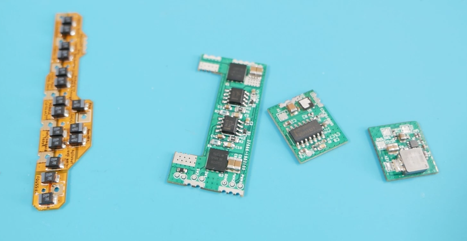
While doing some research, I realized that there were only 2 versions of wired joysticks.
The first are white with grey sticks and the second are black.

The first versions have a large chip, and the second have a small QFN like chip, so I'm obviously going to use the second one.
Screenshot 2023-12-28 at 14.44.27.png

Screenshot 2023-12-28 at 14.57.01.png
Screenshot 2023-12-28 at 14.54.42.png

Early version (white)________________________Smaller chip version (black)

So I reversed the circuit and recreated another custom PCB
Screenshot 2023-12-28 at 14.53.29.png
Screenshot 2023-12-28 at 14.53.44.png

Screenshot 2023-12-28 at 15.11.04.png
Screenshot 2023-12-28 at 15.11.23.png

Screenshot 2023-12-28 at 15.13.03.png

This time it was the right one, everything works fine.
With the exception of the Xbox button, it's connected to 1.8V and not to ground, so I modified it on the circuit afterwards.

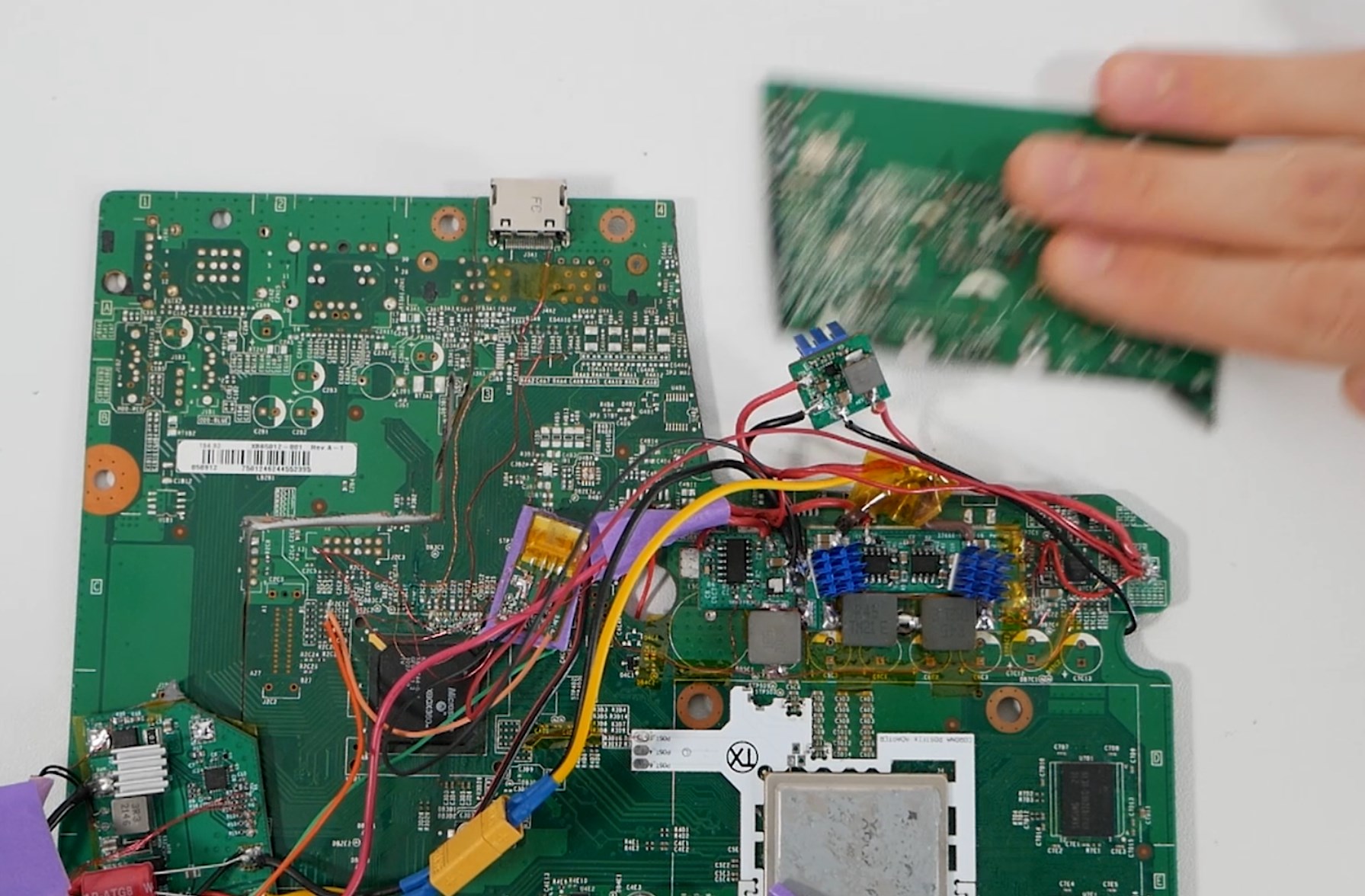
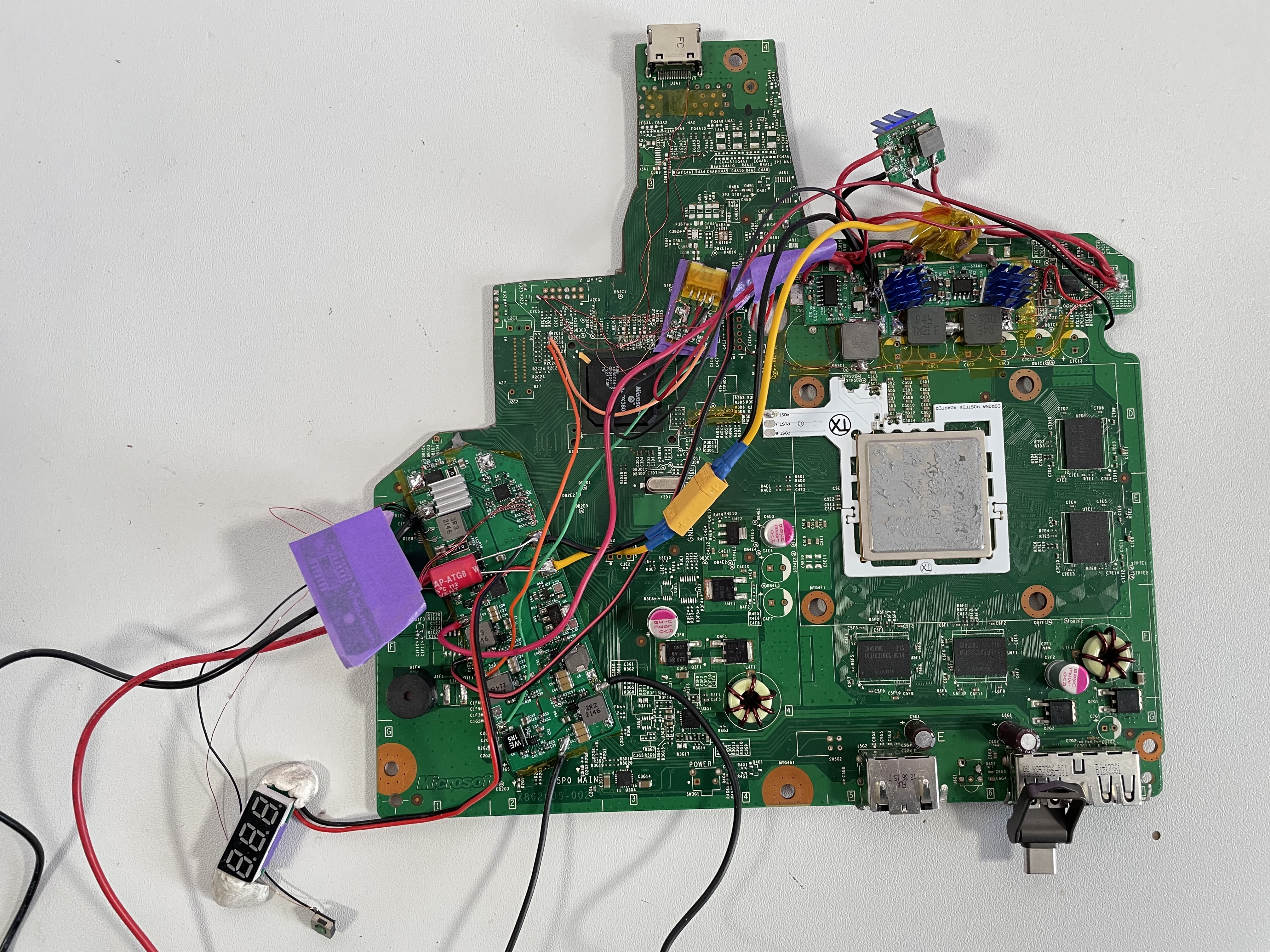
USB C Power Delivery 20V 5A :
The circuit I was using to have PD 20V 5A is the CH224K, it's perfect because it requires very few external components.
I made a custom PCB where I integrated it and also added external USB for the console, as well as all screen control buttons.

As there will be external devices connecting to it I added short-circuit protection for 5V and ESD protection for D+-.

Screenshot 2023-12-28 at 15.19.10.png
Screenshot 2023-12-28 at 15.20.12.png

The schematic above is up to date, on my PCB you can see a modification because I made a mistake in the first circuit version.

I had ordered the components on HQOnline, but as there were no footprints and I couldn't find them anywhere except on Easy EDA, I had to make my PCB there.
I don't like the software at all, KiCad is much better, but it still saved me time, I'd have been too lazy to recreate the footprints, I hate doing that !

Here are the videos related to this part, I didn't go into detail about the 3D modeling and print testing part because I really don't want to go into it again, so I'll leave that in the videos :
 

Benge

.
Joined
May 18, 2020
Messages
201
Likes
689
Location
France
Portables
4 : O-Wii (V1,V2,V2.1)/ BS2
I've just finished working on most of the final review video of this big project, so I'll be able to continue updating this thread !

Battery :
For the battery I'm using 4S 5000mAh 21700 (Lishen LR21700SD).
I connected them in series and spot welded them with 8mm nickel strips in 0.2mm thickness.

To size the strips I used this table : https://endless-sphere.com/forums/download/file.php?id=205284
msedge_ZWf3vWbsCr.png


Then I use a BMS, this one is pretty good and have a connection to add a thermistor for temperature protection which is nice :)
This BMS doesn't have a balance function, so I added one.

It's an active balancer, and unlike resistance balancers, it can balance a much larger current, and it doesn't dissipate this energy as a loss,
since it recharges the cell next to it.
I also cut it a little bit so that it would pass just behind the BMS
msedge_CN8QNVkaFJ.png
msedge_7vfP6ltqGB.png


Here is the finished battery pack, there is one thermistance for the BMS and another one for the charge circuit.
With that I'm sure the battery is secure :D
2E7B72F3-E0B2-4EFD-8C55-FB8B26044603.jpg


Then to know the battery level I didn't want to code,
so I made an electronic circuit with 4 leds and comparators that turn off each led when you go under a define voltage threshold.
kicad_N9O6DURWoM.png


A battery doesn't have a linear discharge curve and its voltage varies with current.
So to find the best threshold which reflects the capacity.

I took battery voltage measurements with the console running to get a realistic current in load (it's pretty consistent between games).
Voltage_VS_Time_Batt_Discharge_LED_voltages.png

then by taking the total playtime I can divide it into shares and that's how I chose my thresholds.
to avoid finding resistance values with complicated calculations or IRL I prefer to use this little online simulator which works very well : http://falstad.com/circuit/

here's what it looks like assembled :
msedge_bBLsQqBuFK.png


An important point !

As the voltage will vary a lot with the battery and the power supply, there's a place on the motherboard to detect that the power supply (12V as standard)
is at the right voltage to start the console.

to trick the console to think we're using 12V, I just use a small linear voltage regulator (7812)
I had used a larger one for testing, which I then replaced with this small one.
The signal is called 12V DET if I remember corectly
CHKSTOP_DETECT_Wire - Copy.jpg
IMG_3570_sus.jpg

An added feature is : it shuts down the console when the battery is around real 5% (11.6V in load)
Perfect for avoiding heavy discharges and prolonging battery life !

All this was seen in episode 9 (see above)
 

Benge

.
Joined
May 18, 2020
Messages
201
Likes
689
Location
France
Portables
4 : O-Wii (V1,V2,V2.1)/ BS2
Safety first !
I wanted protection in case of overheating or thermistor reading problems.
I had no choice but to use a microcontroller.

At first I really didn't want to code, I don't like that and it always takes up a lot of my time.
But it has a lot of advantages, by using a microcontroller I can automatically turn off the console in the event of a problem, manage my fan speed as I want, have a battery indicator with a single RGB LED, and turn on the console with a single button.
That’s a lot of benefit !

Now you have to find which microcontrolle to use :rothink:

Obviously I exclude arduino, because it's crap, it's just good for rapid prototyping, not for making something reliable.
So I compared between STM32 and AVR 8BIT.

I use STM32CubeMX and IDE, with abstraction layer.
I don't quite understand how to use registers yet.

This is basically what I want to do:
Diagramme Securite Xbox 360P.drawio.png

Aa basically I wanted to take a C0 since it's very small (3x3mm), not expensive, and that it's more than enough in terms of function for what I want to do.
msedge_5Tc3md0vFy.png

The problem is that to communicate with my RGB LED I use DMA, and there is no way to stop it, so the LED flashes.
I did the same with a Nucleo F030R8, this time everything worked, and I was able to implement everything I had planned.

The problem is that this MCU doesn't have any smaller package good that I could integrate into a PCB :facepalm:
So I bought another nucleo, I took the MCU that everyone uses, the F103 (same as the blue pill board).

As it's not the same MCU nor the same oscillator frequencies, I had to completely readapt my code.
msedge_HwC1Shm8lY.jpg

but in the end, everything worked !

Then for the package I chose the VQFPN36, and created a PCB.
ST documentation help a lot for that.
I also added a µSD to USB adapter based on GL823K
I thought I would use this with 512Gb µSD to replace the hard drive, but later I realized that it was a problem for several reasons that I will explain later.
kicad_uAy9Wve71h.jpg


I tested all the functions, and everything worked except turning on the console.
When I turn on my power supply, it lights up everything, including my MCU, and the MCU activates a mosfet that sends 1.8V to the Xbox button on the controller for the time it takes to turn on the console.
But nothing worked, I tried N Channel, P Chanel, and even a simple relay !

And nothing works for no reason !!??
I can power ON only by manually pressing the Xbox button.
I don't know why it only works only manually when even though the conditions are the same on the electronic side !!!
msedge_DqYUBkgdCn.png

So the final features are :
  • Battery level indicator : Blue Charge/ PSU pluged in, then fade from green to red, then when 5% batt left -> blink red
  • PWM for cooling fan (controled by a thermistor placed at the VRM location)
  • Burst mode for fan if temp get too hot a little amount of time
  • Auto power OFF if no thermistor is read or if temperature is too low or too high
It's been a very long and tedious process, but I've learned a lot, and I'll be more confident using MCU in other projects now.
 
Top