Worklog Portable Famicom

Trozze

.
Joined
Jun 25, 2018
Messages
15
Likes
16
Location
Sweden
This will be my Portable Famicom worklog, I hope you will enjoy reading it! I will post a lot of pictures.

Some goals:

* Make it organized inside
* All parts should be removable (No hot glue :blush:).
* Reuse as much of the original console as possible
* Turn On/Off with the start-button
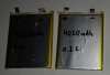
* Battery indicator

I do not have a fancy 3D printer, so no custom case. However, I found something even better :D... I'm going to use the Famicom... as the case! Let's get started!!!

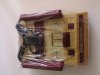
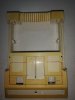
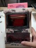
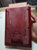
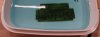
So I got the most ugly Famicom i could find on Ebay:
fami.jpg
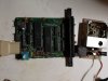
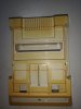
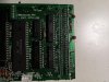
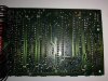
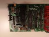
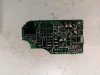
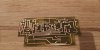
Removing and cleaning the dirty PCB, then testing it, everything works, great!
IMG_20180620_204439.jpg

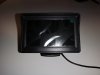
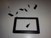
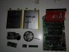
Going to use a standard screen that most people seem to use. Starting with flatting the edges
IMG_20180621_182330.jpg IMG_20180621_183434.jpg

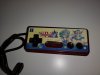
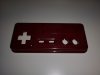
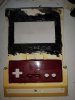
Someone had placed a sticker on the controller, so I had to remove it and the gold decal.
IMG_20180621_191748.jpg IMG_20180621_184129.jpg

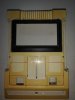
The case has a perfect size for the screen and controller.
Using the Monitor and controller frames, i started marking where to cut and place them using my Dremel.
IMG_20180622_120215.jpg IMG_20180622_122914.jpg IMG_20180622_122923.jpg IMG_20180622_162940.jpg

I am using "ABS Cement" (Old Famicom parts + Acetone) to make a perfect bound with the original case.

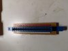
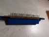
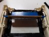
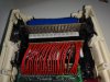
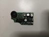
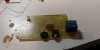
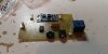
While waiting for i the ABS Cement to harden; I started with the cartridge connector. Removing the connector and replacing it with a newer one with less wear, I mounted it on a perfboard to strengthen it and soldered long pins on the bottom of it so it would be detachable from the motherboard (Will show pictures later).

bild3.jpg bild2.jpg pins.jpg

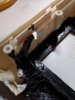
I cut two small holes on both sides of the case so i could slide the cart connector into place.

c1.jpg c2.jpg c3.jpg
 

Trozze

.
Joined
Jun 25, 2018
Messages
15
Likes
16
Location
Sweden
I have done a lot of modifications on the motherboard. :D
Removed the RF-board, removing the old ceramic caps with new SMD, soldered them to the bottom of the PCB.

IMG_20180704_222541.jpg
Also removed the expansion port on the front and the reset switch. Replaced the crystal with a brand new one (some Famicoms crystals have gone bad after some use). Added a 820uF capacitor to the PCB.

IMG_20180704_222506.jpg
Removed the parts that has to do with the video circuit, going to make my own amp. Removed resistor R3, so the microphone audio wont mix with the internal sound. Added a 3-pin connector that the screen will be attached to (Providing 5v, video, Ground). B|

I have also temporary wired up the detachable cartslot - for testing purpose!

IMG_20180704_223428.jpg

Moving on to the audio, I got some broken gamegears from Ebay a while back, that someone had tried to fix.. badly...:facepalm:O.o

IIMG_20180701_2005030.jpg

The GameGear have a nice audio amp pcb with audio control and headphone jack + speaker.
So I started with removing all components on the PCB, the old owner had only removed the caps and soldered on new, and never removed the leaked electrolytic...

IIIMG_20180701_205840.jpg

After that I cleaned everything and soldered new parts in!

IMG_20180706_074653.jpg

I'm not sure were Im going to place the headphone jack, so I've not soldered that in yet.

I'm not done with the case yet, but it's starting to take form.
iiIMG_20180705_202137.jpg IMG_20180705_202146.jpg

These are the batteries I'm going to use, taken from an 1 year old laptop, I charged them full and tested the Famicom+screen and they lasted for about 9 hours! :awesome:
battery.jpg

These are most of the parts I'm going to use for my portable (might change the speaker). I will program the AVR-chip to handle the battery indicator, turning on/off the system, resetting (any maybe more!).;)
Parts.jpg

This might not be the most interesting worklog, but comments are welcome :D!
 

Trozze

.
Joined
Jun 25, 2018
Messages
15
Likes
16
Location
Sweden
Looks nice so far.
Are you going for composite, rgb or hdmi?
Thanks :D! I'm going to use composite for the LCD.

I am currently designing the PCB and programming the AVR-chip that will control most of the stuff; this is why I have not posted anything yet.
I can hopefully post some update later this week! :awesome:

That looks really great, great work so far and keep up the good work
Thank you! :D
 
Joined
Aug 28, 2016
Messages
16
Likes
22
Portables
Made: 0 Own: 1
Sounds good. Anything is a step up from the RF that comes with the original Famicom when it comes to LCD displays. :P
I don't mind composite video for most part; as that is what I grew up using from n64/ps1 till mid way through the PS3/360 years! :XD:
I'm excited to see how you end up implementing it as well as the audio.
Btw, I like the Sharp Twin Famicom myself! ;)
 

Trozze

.
Joined
Jun 25, 2018
Messages
15
Likes
16
Location
Sweden
Sounds good. Anything is a step up from the RF that comes with the original Famicom when it comes to LCD displays. :P
I don't mind composite video for most part; as that is what I grew up using from n64/ps1 till mid way through the PS3/360 years! :XD:
I'm excited to see how you end up implementing it as well as the audio.
Btw, I like the Sharp Twin Famicom myself! ;)
My main console is a RGB Switchless Twin Famicom AN-505-BK :D:D!

Sorry for the late response, life got in the way, but now I am back.:blush:

I have spent several days working on a schematic and designing the PCB that will handle the audio, 5V-regulator, BMS, Relay to turn on the console, Turn on/off.B|

schem.png pcb.png

Etching the PCB

etch.jpg clear pcb.jpg

Drilled holes and started to solder the parts into place

PCB1.jpg PCB2.jpg

PCB3.jpg


Not everything soldered into place, will update when I am done with it.
I am also working on the AVR-chip that will control everything. :awesome:

PS: The PCB will be placed here

bottom.png
 
Top