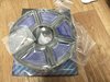
Hi, I'm still working on gathering components and finalizing details, but here are the consumables I've gathered so far ...
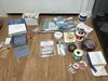
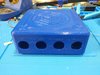
The case is currently printed in gray PLA. However, I have an unopened spool of blue ASA, a full metal throat for my Ender 3 that has not yet been installed, and a 3D printer enclosure I've never used, so if I say I do it here I'll have do follow through, because accountability. Imma make me a blue Noldendo-style Wii Micro!
Also, yes, there are many materials here that are extra/unnecessary, but I've been going through boxes where I've stored everything needed for each unfinished project, finding out how many duplicate things I've bought. I'm trying to keep them together now.