Worklog Nemo's G-wii worklog

Joined
Mar 21, 2021
Messages
86
Likes
16
The silkscreen on the underside of the board has the pin designations.

Also, short spotted
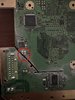
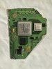
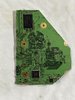
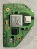
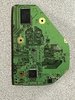
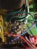
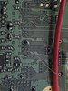
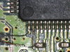
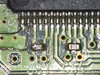
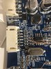
I believe I fixed this short, it's reading a resistance with the ohmeter, but I'm still having issues with a blue screen after powering on.
shorted pins from earlier.jpg

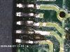
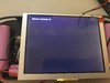
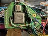
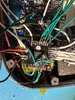
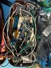
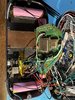
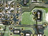
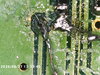
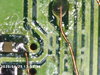
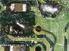
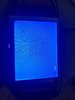
First I removed the composite video wiring, which was giving me a blue screen when wired that way. My wii has patched VGA from RVLoader which I assumed was the cause for the blue screen earlier, however after wiring the VGA wires (images below) I get the same blue screen. I doublechecked all the wires and I'm certain they are going to the correct pins on the screen. I didn't have color coded wires, so I tied a knot on each end to differentiate the ground wire from the live wire, so I don't think I've made any errors as far as hookups. Is my trim the problem? Or any idea where the problem could be located?

All your input is appreciated, thanks in advance.
 

Attachments

Last edited:

Stitches

2 and a Half Dollarydoos
Staff member
.
.
Joined
Feb 5, 2017
Messages
3,815
Likes
3,009
Location
Banana Bender Land, Australia
Portables
6
Ayyyy grats! Yeah that asshole screen and a few others have incorrect silkscreen designators, makes it tricky
 
Joined
Mar 21, 2021
Messages
86
Likes
16
Ayyyy grats! Yeah that asshole screen and a few others have incorrect silkscreen designators, makes it tricky
Yeah it really threw me for a minute, felt pretty bad and just sat there wondering “what did I get wrong” but then it was such a rush when switching the h and v sync actually worked and the screen came up.
 
Last edited:
Joined
Mar 21, 2021
Messages
86
Likes
16
I lifted one of the pads on my GC 2.0, so I ordered a GC 2.0+ from 4layertech, but then I wired ground on my GC 2.0+ to 3.3V on the PMS-2 by mistake and the unit stopped booting. When I first removed the ground wire from the PMS-2 the wii booted up as normal, except now the data wire wasn't working, but since reconnecting the data lines, the wii has stopped booting again. The battery is low so I'm letting it charge, but the 3.3V on the PMS-2 line is only reading 0.2V over ground. Have I fried some internal resistor somewhere in the PMS-2?
 
Last edited:
Joined
Mar 21, 2021
Messages
86
Likes
16
I got a new PMS-PD and PMS-2 from 4-layer, but after changing out the boards, the unit still will not boot. Do you think the wii itself is dead or is the issue now the video lines possibly? Is there a way to test the wii to find out if it is still good or not?

EDIT: If I test resistances on the wii board will that tell me if it is functional or do I need to power the unit and measure potential?
 
Last edited:

Stitches

2 and a Half Dollarydoos
Staff member
.
.
Joined
Feb 5, 2017
Messages
3,815
Likes
3,009
Location
Banana Bender Land, Australia
Portables
6
I got a new PMS-PD and PMS-2 from 4-layer, but after changing out the boards, the unit still will not boot. Do you think the wii itself is dead or is the issue now the video lines possibly? Is there a way to test the wii to find out if it is still good or not?

EDIT: If I test resistances on the wii board will that tell me if it is functional or do I need to power the unit and measure potential?
Checking the resistances will let you know if there's a short, which could indicate internal damage
 

Stitches

2 and a Half Dollarydoos
Staff member
.
.
Joined
Feb 5, 2017
Messages
3,815
Likes
3,009
Location
Banana Bender Land, Australia
Portables
6
If you're asking about the passives you hit by the pre-amp, no. You don't need those, they can be removed with no issue
 

Stitches

2 and a Half Dollarydoos
Staff member
.
.
Joined
Feb 5, 2017
Messages
3,815
Likes
3,009
Location
Banana Bender Land, Australia
Portables
6
Yeah you don't need those. Just make sure you remove the damaged components or they'll cause shorts
 

Stitches

2 and a Half Dollarydoos
Staff member
.
.
Joined
Feb 5, 2017
Messages
3,815
Likes
3,009
Location
Banana Bender Land, Australia
Portables
6
The edges are jagged and need some good sanding, but be careful of the NAND traces.
1686616944177.png

You don't have much margin there, so be careful not to sand into them
 
Joined
Mar 21, 2021
Messages
86
Likes
16
Screen Shot 2023-06-18 at 11.08.18 AM.pngIMG_2149.jpgIMG_2147.jpg
My resistances mostly match the trim resistance thread, though 1.15V over gnd is about twice what most others got. I'm assuming it is fine and moving on. I've also included final trim images.

Since I'm using the PMS-2 with U10 emulation, what do I need to do as far as prepping for the emulator? Do I still need to desolder the components on this trimmed board or can I leave them untouched?
 

Stitches

2 and a Half Dollarydoos
Staff member
.
.
Joined
Feb 5, 2017
Messages
3,815
Likes
3,009
Location
Banana Bender Land, Australia
Portables
6
View attachment 28214View attachment 28215View attachment 28216
My resistances mostly match the trim resistance thread, though 1.15V over gnd is about twice what most others got. I'm assuming it is fine and moving on. I've also included final trim images.

Since I'm using the PMS-2 with U10 emulation, what do I need to do as far as prepping for the emulator? Do I still need to desolder the components on this trimmed board or can I leave them untouched?
Those restances look fine, there's always some variance between trims. For the PMS U10 you don't have to do anything with U5. The U5 does nothing on a trimmed Wii and we just use it as a handy matching footprint to relocate the U10 chip to for convenience. When using the U10 pad on a PMS, you only have to run a bit of magnet wire from the U10 pad on the PMS to the U10 via on the Wii. All the other U10 relocation steps aren't needed
 
Joined
Mar 21, 2021
Messages
86
Likes
16
That's way less steps, but it doesn't make the biggest challenge of actually soldering the magnet wire to the U10 via any easier.
 

Stitches

2 and a Half Dollarydoos
Staff member
.
.
Joined
Feb 5, 2017
Messages
3,815
Likes
3,009
Location
Banana Bender Land, Australia
Portables
6
A fibreglass pencil can be used to safely remove the soldermask from the U10 via and expose more copper. It makes soldering the wire a bit easier, especially if you use some good non-rosin based flux
 
Joined
Mar 21, 2021
Messages
86
Likes
16
More progress. I've wired U10 and the thermristor along with 3.3V, 1.8V, 1.15V and 1V plus ground.

If I am correct, I have to wire still Data +/-, Serial clock and data plus RGB HV sync for VGA plus audio plus the data line on the GC+ (along with the shoulder buttons which have not been wired in yet). I also need to wire the screen controls.

I am terrified to turn the thing on again at this point as well.
 

Attachments

Top