A couple of tips to hopefully make your next trim go a little smoother:
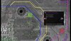
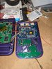
1. Draw out your trim on the backside of the board, as a lot of the cutting lines are sensitive to components and traces on that side.
2. When trimming the board, trim in the direction such that the cutting wheel wants to pull down into the board, rather than jump up and nick the surface of the board. I made a quick paint sketch to demonstrate. Forgive me, I am not an artist:
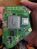
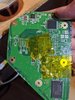
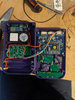
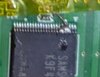
3. I see you used Wesk's method of grinding down the LDO with the dremel before removing it with an iron. It looks like you went down too far and went through multiple layers of the board. This, along with some of the other dremel jumps that went through multiple layers of the board, can cause shorting between the layers, which can really screw things up. I have found that dremeling the LDO is not necessary if you have a good soldering iron. Personally, I carefully clip the legs with a pair of wire cutters, remove them with the iron, then blob a ton of solder on the large pad of the LDO with my iron cranked to ~700F / 370C. If your iron has good heat transfer, this shouldn't be too hard.
4. Most of the solder joints on your boards look pretty cold. Make sure that your iron is a good temperature (I typically keep mine at around 650F / 340C, and use plenty of flux! Make sure to clean any excess residue after every joint to reduce the chance of any phantom shorts. A lot of people recommend Kester 951 liquid flux, and I can attest to its greatness.
I think the most important thing to take away here is the the dremel part. Try this out on one of the unused parts of the board to get a hang of it. You really want to make sure you don't have any slips with the dremel that cut through multiple layers on top of the board, as those are very hard to get rid of without chopping that part of the board off.
Let us know how it goes! Hopefully some of this is helpful to you.

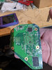
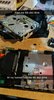 2.2 MB Views: 398
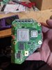
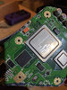
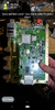 3.5 MB Views: 425
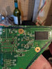