
- Joined
- Mar 10, 2020
- Messages
- 19
- Likes
- 23
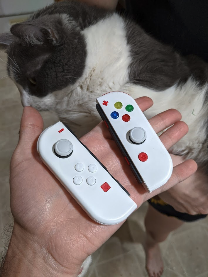
Hi everyone; Long time lurker but first time poster here. I recently got into resin casting and even more recently decided to try my hand at doing some LED mods. These LEDs only turn on when the controllers are connected through Bluetooth and they will not power on in handheld mode (Save my vision lmao)
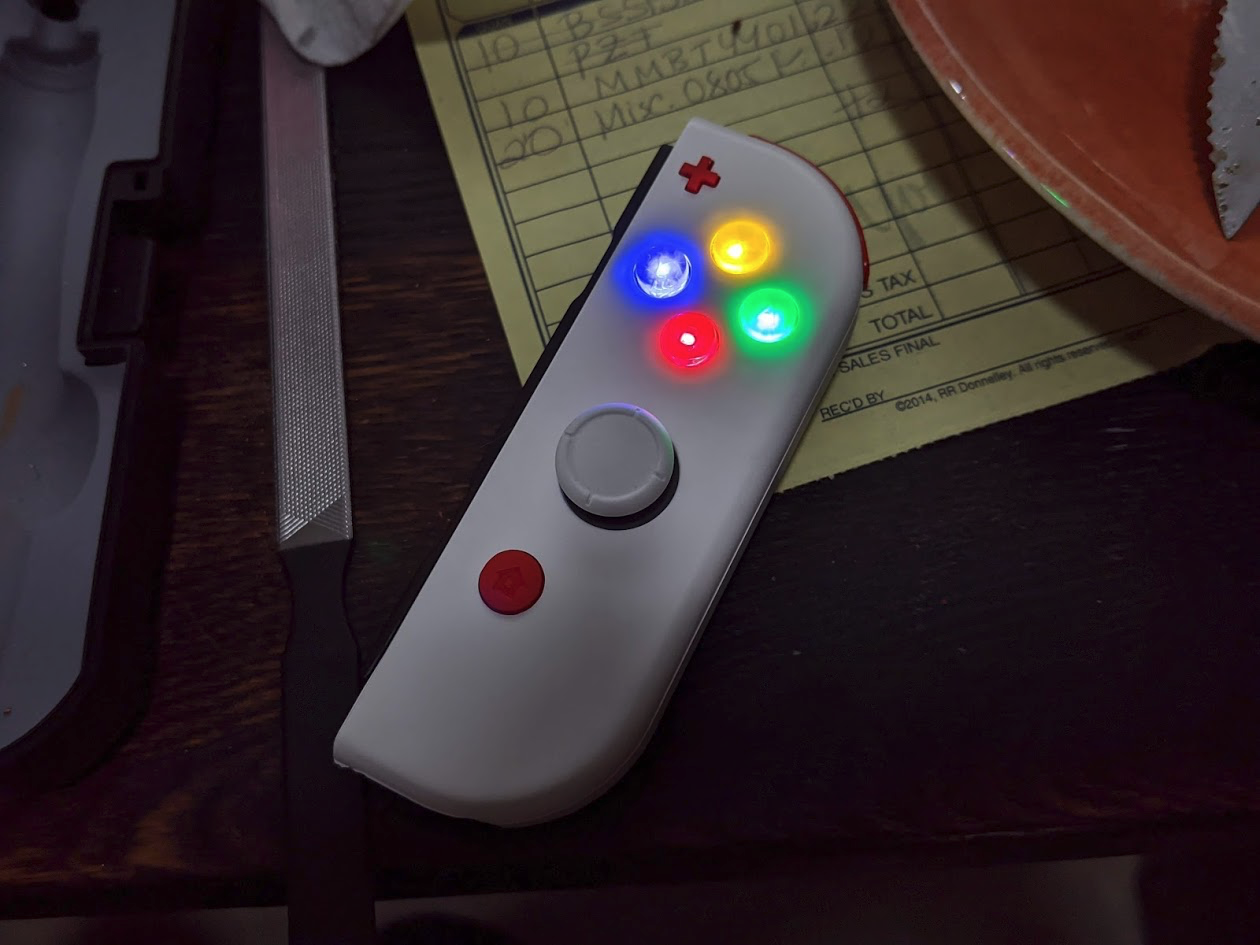
Video overview of the controller:
I got the idea for this project when I saw this video:
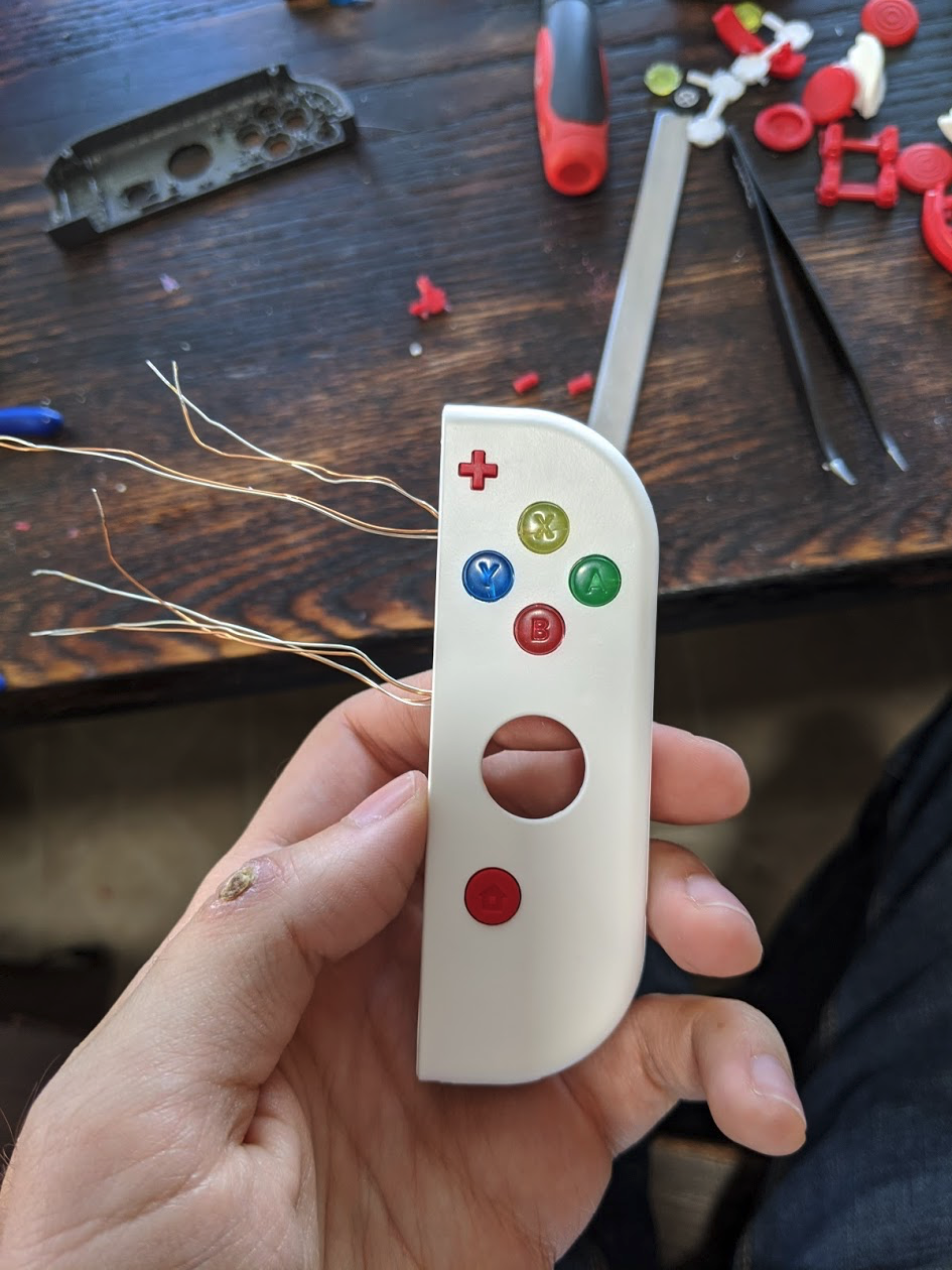
I really wanted to put LEDs into the actual buttons themselves. I opted to resin cast the buttons, and then I had to use a hand drill to create some small holes in the back of the buttons. I also had to use a metal needle file to carve out a small channel for the wires on each button, otherwise the buttons thickness + the thickness of the wire wouldn't let the button depress.
If you're coming to this thread looking for some advice on a mod like this, keep reading! The first video I linked has good information, namely the power, bluetooth signal, and ground pad locations on both joycon controllers. Unfortunately it also has some incorrect information which I'll correct below.
- Joycon power runs around ~3.65v
- Bluetooth status runs at 0.56v
Here's pictures of the various locations to solder to:


Schematic for what I did:
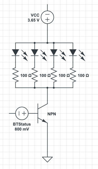
Photo of what your board might look like:

I don't know why I didn't pull out my multimeter and check these numbers first, maybe I had just assumed that since his mod was working in the video that the schematic provided was correct... what a huge waste of time and energy that was! Lesson learned. I found that I didn't need any resistor for BTStatus. Being that I only modded my right Joycon with lights, I guess there's a chance the left Joycon is different but I haven't confirmed.
Video overview of the controller:
I got the idea for this project when I saw this video:
I really wanted to put LEDs into the actual buttons themselves. I opted to resin cast the buttons, and then I had to use a hand drill to create some small holes in the back of the buttons. I also had to use a metal needle file to carve out a small channel for the wires on each button, otherwise the buttons thickness + the thickness of the wire wouldn't let the button depress.
If you're coming to this thread looking for some advice on a mod like this, keep reading! The first video I linked has good information, namely the power, bluetooth signal, and ground pad locations on both joycon controllers. Unfortunately it also has some incorrect information which I'll correct below.
- Joycon power runs around ~3.65v
- Bluetooth status runs at 0.56v
Here's pictures of the various locations to solder to:
Schematic for what I did:
Photo of what your board might look like:
I don't know why I didn't pull out my multimeter and check these numbers first, maybe I had just assumed that since his mod was working in the video that the schematic provided was correct... what a huge waste of time and energy that was! Lesson learned. I found that I didn't need any resistor for BTStatus. Being that I only modded my right Joycon with lights, I guess there's a chance the left Joycon is different but I haven't confirmed.