- Joined
- Jan 18, 2019
- Messages
- 74
- Likes
- 17
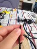
Ok here is my monitor. How would I go about applying the 5v mod and soldering it to the mobo?once its not short circuiting
Attachments
-
 1.2 MB Views: 390
 -
 1.1 MB Views: 416
 -
 1,017.2 KB Views: 338
Ok here is my monitor. How would I go about applying the 5v mod and soldering it to the mobo?once its not short circuiting
Oh yes it's very similar (just not blue). I'll read up about this and try to get the 5v mod to work. Then I need to solder it to my PS2 which should arrive on Monday. I need to look up or ask where to solder the wires to. Thanks for this pageI've only searched quickly, but this looks like your board here - now, be judicious and totally sure that this is correct before you start cutting things up!
https://othermod.com/modify-your-composite-lcd-to-work-at-5v/

Do I need Modbo 5.0? If so, I'll go buy a chip.I've only searched quickly, but this looks like your board here - now, be judicious and totally sure that this is correct before you start cutting things up!
https://othermod.com/modify-your-composite-lcd-to-work-at-5v/
No, use a Free McBoot memory card - those things have a lot of incredible functions for $20NZD. Have a pick through a few more online guides and even watch some of the videos people have made about making a portable PS2 - they really help to fill in odd-ball little questions like this (that you might otherwise lie in bed at night wondering about)Do I need Modbo 5.0? If so, I'll go buy a chip.
")
Ah ok. So I dont need Modbo, gotcha. How about these batteries? Are they safe?No, use a Free McBoot memory card - those things have a lot of incredible functions for $20NZD. Have a pick through a few more online guides and even watch some of the videos people have made about making a portable PS2 - they really help to fill in odd-ball little questions like this (that you might otherwise lie in bed at night wondering about)
Ok cool as I'll buy them then. Also my new PS2 has arrived and the model is 75002.I've got those exact ones from that trader. Now pertaining to "are they safe?" I'd be disinclined to put a chisel through them whilst indoors, but they should do you just fine.
Ok I bought them. They should arrive soon. So how does this audio amp board work that you sent me?I've got those exact ones from that trader. Now pertaining to "are they safe?" I'd be disinclined to put a chisel through them whilst indoors, but they should do you just fine.
I need help! I am up to soldering the screen to the board. I need to know which areas to solder to. I can't find anything online at all! I have found some sites but they have way more wires than I have (I have only two for video, and two for audio). Any help for this?once its not short circuiting
https://bitbuilt.net/forums/index.php?threads/the-definitive-ps2-trimming-guide.1841/I need help! I am up to soldering the screen to the board. I need to know which areas to solder to. I can't find anything online at all! I have found some sites but they have way more wires than I have (I have only two for video, and two for audio). Any help for this?
Thanks but this is hard to understand. I have no idea where to put my AV wires. I need a photo with the wires attached to understand where to put them. My AV monitor has a total of 4 ports for video and audio, 2 ports for the power. I don't have any kind of Luma wire or Chroma wire. Thanks anyways. I also was keeping the AV port so i can output to a bigger TV if I want friends over.https://bitbuilt.net/forums/index.php?threads/the-definitive-ps2-trimming-guide.1841/
Scroll down to the Audio/Video section, yellow goes to composite, and the other wire goes to ground.
Um hehe this is a bit awkward but... I know where to put the yellow wire now. I didn't read your message completelyhttps://bitbuilt.net/forums/index.php?threads/the-definitive-ps2-trimming-guide.1841/
Scroll down to the Audio/Video section, yellow goes to composite, and the other wire goes to ground.
 . Thanks for the help.
I also need help with soldering the monitor to the power port. Any help with this too?https://bitbuilt.net/forums/index.php?threads/the-definitive-ps2-trimming-guide.1841/
Scroll down to the Audio/Video section, yellow goes to composite, and the other wire goes to ground.
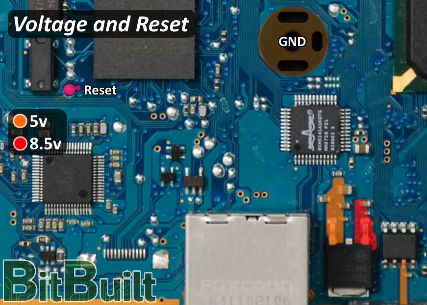
I'm not sure what a custom regulator is. But if it costs money I'd rather use the ones on the PS2. The last sentence you said, I don't understand. Please explainAre you planning on doing custom regulators or just using the regulators in the PS2? If you're using custom regulators just use the 5v reg. If you're using the onboard regulators, you can wire positive to any part labeled 5v on the same page
So just a random point in that orange space? It doesn't matter where I solder it to?Usually the colored wire would be positive and the black would be ground. You only need to wire to one point, not every point.
Thanks, I will. Then I'll solder the wires to it. Would I be able to turn the PS2 on without the disk drive or freemcboot? I also removed the clock battery (CMOS).All the orange points are connected together inside the PS2 board. You are just grabbing the 5v from one of the points to power your screen. I'd suggest reading through our electronics guides
https://bitbuilt.net/forums/index.php?threads/electronics-101-videos.1224/
https://bitbuilt.net/forums/index.php?threads/portables-and-batteries-a-guide-and-explanation.2228/
https://bitbuilt.net/forums/index.php?threads/custom-regulators-an-explanation-and-guide.754/
Yes the ps2 will boot without a disc drive, free mcboot, or cmos battery.Thanks, I will. Then I'll solder the wires to it. Would I be able to turn the PS2 on without the disk drive or freemcboot? I also removed the clock battery (CMOS).
Cool thanks Gman. Love your GS2. I am using the PS2's power supply until my battery charger board arrives.Yes the ps2 will boot without a disc drive, free mcboot, or cmos battery.
looks like yout coming along good. right noe tryna build cash to buy a controllerCool thanks Gman. Love your GS2. I am using the PS2's power supply until my battery charger board arrives.